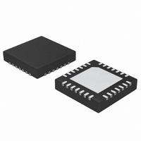
ATA5278-PKQI Atmel, ATA5278-PKQI Datasheet - Page 22

ATA5278-PKQI
Manufacturer Part Number
ATA5278-PKQI
Description
IC ANTENNA DVR STAND-ALONE 28QFN
Manufacturer
Atmel
Type
Stand Alone Antenna Driverr
Datasheet
1.ATA5278-PKQI.pdf
(34 pages)
Specifications of ATA5278-PKQI
Rf Type
TPM
Frequency
125kHz
Package / Case
28-VFQFN
Maximum Operating Temperature
+ 105 C
Mounting Style
SMD/SMT
Minimum Operating Temperature
- 40 C
Lead Free Status / RoHS Status
Lead free / RoHS Compliant
Features
-
Lead Free Status / Rohs Status
Lead free / RoHS Compliant
Other names
ATA5278-PKQITR
3.18
3.19
3.20
Figure 3-16. Typical Application Circuit With ATA5278
22
MODACTIVE Output Pin
Internal Supply Unit
Application Hints
receiver
ATA5278
(min. 7V)
LF
VBATT
GND
Data
C4
Ant
+
L
The MODACTIVE pin of the ATA5278 can be used to directly control a timer/counter stage of
the microcontroller. The signal indicates LF data modulation activity. In conjunction with suited
timers and counting stages in the microcontroller, it enables the software to precisely know the
progress of the LF data transmission. For further details, see
3-10 on page 14
The ATA5278 is equipped with an internal supply unit that provides supply and reference volt-
ages and currents. This unit is directly supplied by the VBATT pin. During power-down mode,
only the 5V voltage regulator is active. This regulator requires an external capacitor applied to
the VDD pin because during operations high peak currents may occur which must be buffered
by the external device. For further details on this issue, please refer to the section
Hints” on page
The Power-On-Reset (POR) is also generated in the internal supply section. The VDD voltage
level is monitored permanently and compared with the regular output level. As soon as the
actual level is lower than the POR threshold, V
30 µs.
The following
A
HVNMOS
R
D2
C5
Shunt
T1
CBOOST
VSHUNT
PGND1
PGND2
PGND3
DRV1
QSC
VDS
Figure 3-16
D1
22.
in the section
AGND
zero crossing
Current and
C2
sensing
converter
HS driver
LS driver
control
Boost
L1
sketches an application using the ATA5278.
DGND
“LF Data Modulation” on page
Driver control
ATA5278
regulator
SCANE
logic
5V
C3
+
C1
TEST
POR
Oscillator
Control
register
status
and
, a reset is triggered and held for at least
LF data buffer
interface
Voltage
Figure 3-9 on page 14
13.
SPI
MODACTIVE
S_CS
S_CLK
S_DI
S_DO
Microcontroller supply
controller
VDD
N_RES
P_IN1
P_IN2
S_CS
S_CLK
S_DI
S_DO
Micro
4832D–RKE–12/07
“Application
and
Figure


