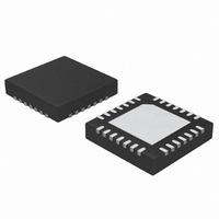
ATA5278-PKQI Atmel, ATA5278-PKQI Datasheet - Page 18

ATA5278-PKQI
Manufacturer Part Number
ATA5278-PKQI
Description
IC ANTENNA DVR STAND-ALONE 28QFN
Manufacturer
Atmel
Type
Stand Alone Antenna Driverr
Datasheet
1.ATA5278-PKQI.pdf
(34 pages)
Specifications of ATA5278-PKQI
Rf Type
TPM
Frequency
125kHz
Package / Case
28-VFQFN
Maximum Operating Temperature
+ 105 C
Mounting Style
SMD/SMT
Minimum Operating Temperature
- 40 C
Lead Free Status / RoHS Status
Lead free / RoHS Compliant
Features
-
Lead Free Status / Rohs Status
Lead free / RoHS Compliant
Other names
ATA5278-PKQITR
3.14
18
Boost Converter
ATA5278
Figure 3-14. Integrator Output Current on CINT Pin
As can be seen in
from the external capacitor depending on the voltage at the VSHUNT pin. Note that the shown
values for VSHUNT are only valid if maximum antenna current (i.e., 1 A
resistor of 1 ) is selected. When the input voltage reaches the desired value (e.g., 1V), no cur-
rent is flowing through the CINT pin and the voltage over the capacitor is not changing. This
voltage influences the output voltage of the boost converter. Note that the lower the voltage on
the integration capacitor, the higher the output voltage of the boost converter will be. The maxi-
mum output voltage is 40V.
The ATA5278 provides the supply current for its driver stage by means of a Switch Mode Power
Supply (SMPS) in boost configuration. A low-side switch that charges the inductor, and the
therefore needed control circuitry is integrated. The other necessary components such as the
inductor, the free-wheeling diode and the charging capacitor have to be applied externally. For
further details, please refer to the section
The SMPS control circuitry is in current-mode configuration. This means that the current through
the coil charging transistor (i.e., the current through the VL1..3 and the PGND1..3 pins) is mea-
sured and compared to a reference current in each switching period. Should the measured value
exceed the reference value, the transistor is switched off and the inductor then discharges its
energy through the free-wheeling diode to the charging capacitor. The reference current is gen-
erated from the voltage on the CINT pin, hence the integrator output voltage.
Figure 3-15 on page
-10
-20
-30
30
20
10
0
0.5
0.6
0.7
Voltage at VSHUNT pin (V)
21, a current is charged into, respectively discharged
0.8
“Application Hints” on page
0.9
1.0
1.1
1.2
1.3
22.
peak
1.4
when using a shunt
4832D–RKE–12/07


