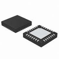
ATA5278-PKQI Atmel, ATA5278-PKQI Datasheet - Page 23

ATA5278-PKQI
Manufacturer Part Number
ATA5278-PKQI
Description
IC ANTENNA DVR STAND-ALONE 28QFN
Manufacturer
Atmel
Type
Stand Alone Antenna Driverr
Datasheet
1.ATA5278-PKQI.pdf
(34 pages)
Specifications of ATA5278-PKQI
Rf Type
TPM
Frequency
125kHz
Package / Case
28-VFQFN
Maximum Operating Temperature
+ 105 C
Mounting Style
SMD/SMT
Minimum Operating Temperature
- 40 C
Lead Free Status / RoHS Status
Lead free / RoHS Compliant
Features
-
Lead Free Status / Rohs Status
Lead free / RoHS Compliant
Other names
ATA5278-PKQITR
4832D–RKE–12/07
The external components used in this schematic are listed in
Table 3-5.
The following basic hints should be considered when designing an application with the
ATA5278.
• Principally, the values for the external choke and the storage capacitor used in the
• The clock supply for the ATA5278 can be either an active clock source connected to the OSCI
• The external HV-MOSFET for the QSC feature should have a low R
• The VIF pin must be connected to the supply voltage with which the microcontroller and
• The VDD pin is intended to be connected to a stabilizing capacitor only. It is not suited for
• The bootstrap capacitor C5 should not exceed values of 22 nF, as the internal charging and
• The value of the integrator capacitor C2 influences the current regulation speed. The higher
• The power dissipation of the ATA5278 mainly depends on the supply voltage and the
Element
switched-mode power supply are not fixed, several performance factors, however, are directly
linked to these values. The parameters given in
to the needs of the internal circuitry and the application.
pin, or a passive device like a crystal or a ceramic resonator. When using a crystal, the
prolonged oscillation build-up time (typically up to 1 ms) needs to be considered. Full
functionality of the chip will only be available after the oscillation has reached a stable state.
contributes to the quality factor of the LC antenna circuitry. Furthermore, only standard gate
input types may be used. TTL-compatible gate inputs might get destroyed by the driving
voltage of the QSC pin.
possible other SPI bus members are driving the SPI bus.
driving any loads.
clamping circuitry can handle only limited currents.
the capacitor, the slower the supply voltage for the antenna driver stage and thus the current
in the antenna is changed. For more details, please refer to the section
on page
selected antenna current. It is strongly recommended to solder the exposed die pad to the
PCB and to provide vias from the top layer (chip soldering side) to the bottom layer, on which
a copper plate, as big in size as possible, can dissipate the heat. This plate can be connected
to ground.
XTAL
D1
D2
C1
C2
C3
C4
C5
R1
L1
T1
17.
List of Used Components
Description
Standard diode
Fast Shottky diode, V
Choke, I
Storage capacitor, C
Ceramic (chip) capacitor, 33 nF
Ceramic (chip) capacitor, C
Low ESR capacitor, 4,7 µF
Ceramic (chip) capacitor, C = 10 nF, V
Shunt resistor, R = 1 (±1%), P
Crystal or ceramic resonator, f
High voltage N-channel MOSFET, V
SAT
4A, R
ESR
BR
220 µF, V
50 m , L = 22 µH
50V, I
C
150 nF
RES
max
D
= 8 MHz
C
22 µF, V
50 VDC
2.5 A
DS,max
0.6W
100 nF
Table 3-5 on page 23
50 VDC
600 VDC, C
50 VDC, R
Table
ESR
GS
3-5.
DSon
2.5 nF
0.8
are already optimized
“Current Regulation”
value, as this value
ATA5278
23


