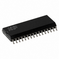
MFRC50001T/0FE,112 NXP Semiconductors, MFRC50001T/0FE,112 Datasheet - Page 30

MFRC50001T/0FE,112
Manufacturer Part Number
MFRC50001T/0FE,112
Description
IC MIFARE READER 32-SOIC
Manufacturer
NXP Semiconductors
Series
MIFARE®r
Specifications of MFRC50001T/0FE,112
Rf Type
Read Only
Frequency
13.56MHz
Features
ISO14443-A, ISO14443-B, ISO15693
Package / Case
32-SOIC (0.300", 7.50mm Width)
Product
RFID Readers
Operating Temperature Range
- 25 C to + 85 C
Lead Free Status / RoHS Status
Lead free / RoHS Compliant
Lead Free Status / RoHS Status
Lead free / RoHS Compliant, Lead free / RoHS Compliant
Other names
568-2222-5
935268039112
MFRC500
MFRC51T0FED
935268039112
MFRC500
MFRC51T0FED
Available stocks
Company
Part Number
Manufacturer
Quantity
Price
Part Number:
MFRC50001T/0FE,112
Manufacturer:
NXP/恩智浦
Quantity:
20 000
NXP Semiconductors
MFRC500_33
Product data sheet
PUBLIC
Fig 10. Receiver circuit block diagram
RX
ClkQDelay[4:0]
DEMODULATOR
9.10.1 Receiver circuit block diagram
CONVERSION
9.9.4 Pulse width
9.10 Receiver circuit
I-clock
13.56 MHz
I TO Q
ClkQCalib
The envelope carries the data signal information that is transmitted to the card. It is an
encoded data signal based on the Miller code. In addition, each pause of the Miller
encoded signal is again encoded as a pulse of a fixed width. The width of the pulse is
adjusted using the ModWidth register. The pulse width (t
where the frequency constant (f
The MFRC500 uses an integrated quadrature demodulation circuit enabling it to extract
the ISO/IEC 14443 A compliant subcarrier from the 13.56 MHz ASK modulated signal
applied to pin RX.
The quadrature demodulator uses two different clocks (Q-clock and I-clock) with a
phase-shift of 90° between them. Both resulting subcarrier signals are amplified, filtered
and forwarded to the correlation circuitry. The correlation results are evaluated, digitized
and then passed to the digital circuitry. Various adjustments can be made to obtain
optimum performance for all processing units.
Figure 10
broken down in to several steps. Quadrature demodulation of the 13.56 MHz carrier signal
is performed. To achieve the optimum performance, automatic Q-clock calibration is
recommended (see
The demodulated signal is amplified by an adjustable amplifier. A correlation circuit
calculates the degree of similarity between the expected and the received signal. The
BitPhase register enables correlation interval position alignment with the received signal’s
bit grid. In the evaluation and digitizer circuitry, the valid bits are detected and the digital
results are sent to the FIFO buffer. Several tuning steps are possible for this circuit.
t
w
Q-clock
VRxFollI
=
2
ClkQ180Deg
clock
ModWidth
------------------------------------ -
VRxFollQ
shows the block diagram of the receiver circuit. The receiving process can be
Gain[1:0]
f
clk
VRxAmpI
All information provided in this document is subject to legal disclaimers.
+
1
Section 9.10.2.1 on page
VRxAmpQ
Rev. 3.3 — 15 March 2010
CORRELATION
BitPhase[7:0]
CIRCUITRY
048033
TestAnaOutSel
clk
) = 13.56 MHz.
to
VCorrDI
Highly Integrated ISO/IEC 14443 A Reader IC
VCorrNI
31).
VCorrDQ
VCorrNQ
MinLevel[3:0]
w
CollLevel[3:0]
) is calculated using
VEvalR
EVALUATION
CIRCUITRY
DIGITIZER
AND
RxWait[7:0]
VEvalL
MFRC500
RcvClkSell
© NXP B.V. 2010. All rights reserved.
001aak615
s_valid
s_data
s_coll
s_clock
Equation 9
30 of 110
(9)


