DEMOKITCRX14 STMicroelectronics, DEMOKITCRX14 Datasheet - Page 26
DEMOKITCRX14
Manufacturer Part Number
DEMOKITCRX14
Description
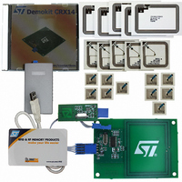
RFID EVALUATION KIT ISO14443-B
Manufacturer
STMicroelectronics
Type
Development kitr
Specifications of DEMOKITCRX14
Contents
CD-ROM, CRX14 Board, USB Transceiver, Samples and Documentation
Processor To Be Evaluated
CRX14
Interface Type
I2C
Operating Supply Voltage
5 V
For Use With/related Products
CRX14
Lead Free Status / RoHS Status
Contains lead / RoHS non-compliant
Other names
497-3704
Available stocks
Company
Part Number
Manufacturer
Quantity
Price
Company:

Part Number:
DEMOKITCRX14
Manufacturer:
HITACHI
Quantity:
340


CRX14
TAG ACCESS USING THE CRX14 COUPLER
In all the following I²C commands, the last three
bits of the Device Select Code can be replaced by
any of the three-bit binary values (000, 001, 010,
011, 100, 101, 110, 111). These values are linked
to the logic levels applied to the E2, E1 and E0
pads of the CRX14.
Standard TAG Command Access Description
Standard PICC commands, like Read and Write,
are generated by the CRX14 using the Input/Out-
put Frame Register.
When the host needs to send a standard frame
command to the PICC, it first has to internally gen-
erate the complete frame, with the command code
followed by the command parameters. Only the
two CRC Bytes should not be generated, as the
CRX14 automatically adds them during the RF
transmission.
When the frame is ready, the host has to write the
request frame into the Input/Output Frame Regis-
ter using the I²C write command specified in
Figure 29. Standard TAG Command: Request Frame Transmission
Figure 30. Standard TAG Command: Answer Frame Reception
26/40
I²C
RF
I²C
RF
S
T
A
R
T
Device
TAG
SOF
Select
Code
SOF
Register
Address
Output
Input/
01h
Data 1
TAG
Data
Request
Length
Frame
N
Data 2
TAG
Data
Data 1
Code
Cmd
TAG
Data
TAG
Data
Param
Data 2
Data P
TAG
Data
Param
Data
Param
CRC
TAG
CRC
Data N
S
T
O
P
Fig-
CRC
TAG
CRC
CRX14
SOF
SOF
EOF
TAG
EOF
ure 14., page
CRX14 inserts the I²C Bytes in the required ISO
character format (
mit the request frame to the PICC. Once the RF
transmission is over, the CRX14 waits for the
PICC to send an answer frame.
If the PICC answers, the characters received (
ure
into the Input/Output Frame Register, as specified
in
CRX14 disconnects itself from the I²C bus. On re-
ception of the PICC EOF, the CRX14 checks the
CRC and reconnects itself to the I²C bus.
The host can then get the PICC answer frame by
issuing an Input/Output Frame Register Read on
the I²C bus, as specified in Figures
If no answer from the PICC is detected after a
time-out delay, fixed in the Parameter Register
(bits b
is set as specified in
Data 1
Table 4.
TAG
Cmd
Code
S
T
A
R
T
27.) are demodulated, decoded and stored
Device
Select
Code
5
and b
Data 2
Param
Register
Address
During the entire RF transmission, the
Output
Input/
01h
18. After the I²C STOP condition, the
6
), the Input/Output Frame Register
Param
Data
Answer
Length
Frame
P
Figure
Table 4.
Data N
Param
Data 1
TAG
Data
21.) and starts to trans-
TAG
Data
CRC
CRC
Data 2
TAG
Data
CRC
CRC
15
Data
and 16.
Data P
SRX14
TAG
Data
EOF
EOF
ai09260
ai09261
Fig-
S
T
O
P
Related parts for DEMOKITCRX14
Image
Part Number
Description
Manufacturer
Datasheet
Request
R

Part Number:
Description:
DEMO KIT M24LR-64-R
Manufacturer:
STMicroelectronics
Datasheet:

Part Number:
Description:
STMicroelectronics [RIPPLE-CARRY BINARY COUNTER/DIVIDERS]
Manufacturer:
STMicroelectronics
Datasheet:
Part Number:
Description:
STMicroelectronics [LIQUID-CRYSTAL DISPLAY DRIVERS]
Manufacturer:
STMicroelectronics
Datasheet:

Part Number:
Description:
BOARD EVAL FOR MEMS SENSORS
Manufacturer:
STMicroelectronics
Datasheet:
Part Number:
Description:
NPN TRANSISTOR POWER MODULE
Manufacturer:
STMicroelectronics
Datasheet:
Part Number:
Description:
TURBOSWITCH ULTRA-FAST HIGH VOLTAGE DIODE
Manufacturer:
STMicroelectronics
Datasheet:
Part Number:
Description:
Manufacturer:
STMicroelectronics
Datasheet:
Part Number:
Description:
DIODE / SCR MODULE
Manufacturer:
STMicroelectronics
Datasheet:
Part Number:
Description:
DIODE / SCR MODULE
Manufacturer:
STMicroelectronics
Datasheet:
Part Number:
Description:
Search -----> STE16N100
Manufacturer:
STMicroelectronics
Datasheet:
Part Number:
Description:
Search ---> STE53NA50
Manufacturer:
STMicroelectronics
Datasheet:
Part Number:
Description:
NPN Transistor Power Module
Manufacturer:
STMicroelectronics
Datasheet: