DEMOKITCRX14 STMicroelectronics, DEMOKITCRX14 Datasheet - Page 23
DEMOKITCRX14
Manufacturer Part Number
DEMOKITCRX14
Description
RFID EVALUATION KIT ISO14443-B
Manufacturer
STMicroelectronics
Type
Development kitr
Specifications of DEMOKITCRX14
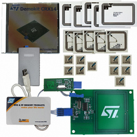
Contents
CD-ROM, CRX14 Board, USB Transceiver, Samples and Documentation
Processor To Be Evaluated
CRX14
Interface Type
I2C
Operating Supply Voltage
5 V
For Use With/related Products
CRX14
Lead Free Status / RoHS Status
Contains lead / RoHS non-compliant
Other names
497-3704
Available stocks
Company
Part Number
Manufacturer
Quantity
Price
Company:

Part Number:
DEMOKITCRX14
Manufacturer:
HITACHI
Quantity:
340


Input RF Data Transfer from the PICC to the
CRX14 (Answer Frame)
The CRX14 uses the ISO14443 type-B retro-mod-
ulation scheme which is demodulated and decod-
ed by the RF
The modulation is obtained by modifying the PICC
current consumption (load modulation). This load
modulation induces an H-field variation, by cou-
pling, that is detected by the CRX14 RF
Figure 24. Wave Received using BPSK Sub-carrier Modulation
Transmission Format of Answer Frame
Characters
The PICC should use the same character format
as that used for output data transfer (see
21.).
1/847kHz
V RFIN
IN
circuitry.
phase shift
1/106kHz
IN
input as
Figure
a voltage variation on the antenna. The RF
demodulates this variation and decodes the infor-
mation received from the PICC.
Data must be transmitted using a 847kHz, BPSK
modulated sub-carrier frequency, f
Figure
In BPSK, all data state transitions (from ‘0’ to ‘1’ or
from ‘1’ to ‘0’) are encoded by phase shift keying
the sub-carrier.
An Answer Frame includes the SOF, data, CRC
and the EOF, as illustrated in
transfer rate is 106 kbit/s.
The CRX14 will also accept Answer Frames that
do not contain the SOF and EOF delimiters, pro-
vided that these Frames are correctly set in the
Parameter Register. (See
V OFFSET
24., and as specified in ISO14443 type-B.
V
RET
V DYN
PICC data bit to be transmitted
to the CRX14.
847kHz BPSK, resulting signal
generated by the PICC for the
load modulation.
Figure
t
Load modulation effect on
the H-Field received on the
CRX14 RF IN input pad
Figure
27.).
S
, as shown in
27.. The data
CRX14
IN
ai09253
23/40
input
Related parts for DEMOKITCRX14
Image
Part Number
Description
Manufacturer
Datasheet
Request
R

Part Number:
Description:
DEMO KIT M24LR-64-R
Manufacturer:
STMicroelectronics
Datasheet:

Part Number:
Description:
STMicroelectronics [RIPPLE-CARRY BINARY COUNTER/DIVIDERS]
Manufacturer:
STMicroelectronics
Datasheet:
Part Number:
Description:
STMicroelectronics [LIQUID-CRYSTAL DISPLAY DRIVERS]
Manufacturer:
STMicroelectronics
Datasheet:

Part Number:
Description:
BOARD EVAL FOR MEMS SENSORS
Manufacturer:
STMicroelectronics
Datasheet:
Part Number:
Description:
NPN TRANSISTOR POWER MODULE
Manufacturer:
STMicroelectronics
Datasheet:
Part Number:
Description:
TURBOSWITCH ULTRA-FAST HIGH VOLTAGE DIODE
Manufacturer:
STMicroelectronics
Datasheet:
Part Number:
Description:
Manufacturer:
STMicroelectronics
Datasheet:
Part Number:
Description:
DIODE / SCR MODULE
Manufacturer:
STMicroelectronics
Datasheet:
Part Number:
Description:
DIODE / SCR MODULE
Manufacturer:
STMicroelectronics
Datasheet:
Part Number:
Description:
Search -----> STE16N100
Manufacturer:
STMicroelectronics
Datasheet:
Part Number:
Description:
Search ---> STE53NA50
Manufacturer:
STMicroelectronics
Datasheet:
Part Number:
Description:
NPN Transistor Power Module
Manufacturer:
STMicroelectronics
Datasheet: