DEMOKITCRX14 STMicroelectronics, DEMOKITCRX14 Datasheet - Page 25
DEMOKITCRX14
Manufacturer Part Number
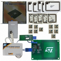
DEMOKITCRX14
Description
RFID EVALUATION KIT ISO14443-B
Manufacturer
STMicroelectronics
Type
Development kitr
Specifications of DEMOKITCRX14
Contents
CD-ROM, CRX14 Board, USB Transceiver, Samples and Documentation
Processor To Be Evaluated
CRX14
Interface Type
I2C
Operating Supply Voltage
5 V
For Use With/related Products
CRX14
Lead Free Status / RoHS Status
Contains lead / RoHS non-compliant
Other names
497-3704
Available stocks
Company
Part Number
Manufacturer
Quantity
Price
Company:

Part Number:
DEMOKITCRX14
Manufacturer:
HITACHI
Quantity:
340


Transmission Frame
The Request Frame transmission must be fol-
lowed by a minimum delay, t
which no ASK or BPSK modulation occurs, before
the Answer Frame can be transmitted. t
minimum time required by the CRX14 to switch
from transmission mode to reception mode, and
should be inserted after each frame. After t
Figure 27. Example of a Complete Transmission Frame
CRC
The 16-bit CRC used by the CRX14 follows the
ISO14443 type B recommendation. For further in-
formation, please see
The two CRC Bytes are present in all Request and
Answer Frames, just before the EOF. The CRC is
calculated on all the Bytes between the SOF and
the CRC Bytes.
Upon transmission of a Request from the CRX14,
the PICC verifies that the CRC value is valid. If it is
invalid, it discards the frame and does not answer
the CRX14.
Upon reception of an Answer from the PICC, the
CRX14 verifies that the CRC value is valid. If it is
the CRX14
Sent by
Case of Answer Frame with SOF & EOF
Case of Answer Frame without SOF & EOF
at 106Kb/s
Sent by the PICC
SOF
12 bits
Output Data Transfer using ASK Modulation
10 bits
Cmd
APPENDIX A., page
10 bits
Data
t DR
0
(see
10 bits
CRC
Table
10 bits
CRC
0
13.), in
38.
is the
0
, the
10 bits
EOF
64/f s Min
64/f s Min
13.56MHz carrier frequency is modulated by the
PICC at 847kHz for a minimum time of t
ble
t
represents the start bit (‘0’) of the Answer SOF (or
the start bit ‘0’ of the first data character in non
SOF/EOF mode).
invalid, it stores the value FFh in the Input/Output
Frame Register.
The CRC is transmitted Least Significant Byte first.
Each Byte is transmitted Least Significant Bit first.
Figure 28. CRC Transmission Rules
1
t 0
t 0
, the first phase transition generated by the PICC
LSBit
t WDG
t WDG
13.) to allow the CRX14 to synchronize. After
f s = 847.5kHz
80/f s Min
80/f s Min
Sync
Sync
CRC 16 (8 bits)
t 1
t 1
Input Data Transfer using 847kHz BPSK Modulation
LSByte
10 bits
12 or 13
SOF
Data
bits
MSBit LSBit
10 bits
Data
10 bits
Data
10 bits
Data
10 bits
CRC
CRC 16 (8 bits)
10 bits
CRC
MSByte
10 bits
CRC
10 bits
CRC
12 or 13
EOF
1
bits
(see
MSBit
CRX14
ai09255
ai09256
25/40
Ta-
Related parts for DEMOKITCRX14
Image
Part Number
Description
Manufacturer
Datasheet
Request
R

Part Number:
Description:
DEMO KIT M24LR-64-R
Manufacturer:
STMicroelectronics
Datasheet:

Part Number:
Description:
STMicroelectronics [RIPPLE-CARRY BINARY COUNTER/DIVIDERS]
Manufacturer:
STMicroelectronics
Datasheet:
Part Number:
Description:
STMicroelectronics [LIQUID-CRYSTAL DISPLAY DRIVERS]
Manufacturer:
STMicroelectronics
Datasheet:

Part Number:
Description:
BOARD EVAL FOR MEMS SENSORS
Manufacturer:
STMicroelectronics
Datasheet:
Part Number:
Description:
NPN TRANSISTOR POWER MODULE
Manufacturer:
STMicroelectronics
Datasheet:
Part Number:
Description:
TURBOSWITCH ULTRA-FAST HIGH VOLTAGE DIODE
Manufacturer:
STMicroelectronics
Datasheet:
Part Number:
Description:
Manufacturer:
STMicroelectronics
Datasheet:
Part Number:
Description:
DIODE / SCR MODULE
Manufacturer:
STMicroelectronics
Datasheet:
Part Number:
Description:
DIODE / SCR MODULE
Manufacturer:
STMicroelectronics
Datasheet:
Part Number:
Description:
Search -----> STE16N100
Manufacturer:
STMicroelectronics
Datasheet:
Part Number:
Description:
Search ---> STE53NA50
Manufacturer:
STMicroelectronics
Datasheet:
Part Number:
Description:
NPN Transistor Power Module
Manufacturer:
STMicroelectronics
Datasheet: