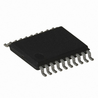
AT86RF401U-XI Atmel, AT86RF401U-XI Datasheet - Page 41

AT86RF401U-XI
Manufacturer Part Number
AT86RF401U-XI
Description
IC MICRO TX RF W/AVR 20-TSSOP
Manufacturer
Atmel
Datasheet
1.AT86RF401U-6GS.pdf
(52 pages)
Specifications of AT86RF401U-XI
Frequency
264MHz ~ 456MHz
Applications
Garage Opener, RKE, Telemetry
Modulation Or Protocol
ASK, OOK
Data Rate - Maximum
10 kbps
Power - Output
6dBm
Current - Transmitting
23.2mA
Data Interface
PCB, Surface Mount
Antenna Connector
PCB, Surface Mount
Memory Size
2KB Flash, 128 Byte EEPROM, 128Byte SRAM
Voltage - Supply
2 V ~ 5 V
Operating Temperature
-40°C ~ 85°C
Package / Case
20-TSSOP
Lead Free Status / RoHS Status
Contains lead / RoHS non-compliant
Features
-
Other names
AT86RF401U
Notes:
1424F–RKE–12/03
Normal Mode
(RESETB = 1)
SPI Mode
(RESETB = 0)
1. IO_ENAB register is NOT used for SPI pins.
2. In SPI mode, the I/O registers may be directly accessed via the SPI interface. Txkey, lockdetect may be output using this
mode.
(Output)
(Output)
txkey
txkey
I/O5
• Bits[6:5]: AVR System Clock Select
These bits select the divide value of the XTALB input that is used to produce the AVR
System Clock.
Table 20. AVR Clock Select Definition
This clock select value may be programmed on the fly by either the AVR processor in
normal operation or by an I/O write SPI command during SPI mode. Note that during
SPI mode, the I/O and serial programming logic runs at XTALB/16 frequency.
• Bit[4]: Test Mode
When this bit is set to “1”, the part enters test mode. The I/O pins, if enabled, assume
the following functionality:
• Bit[3]: Battery Dead
Indicates battery is dead. Only readable by SPI interface.
• Bit[2]: Battery Low Indicator
This bit is identical to Bit[7] of Battery Low Configuration Register ($35). When Bit[6] of
Battery Low Configuration Register ($35) is set (Battery Low Valid), a set bit in this loca-
tion indicates that the battery voltage is lower than the voltage level that is determined
by Bits[5:0] of Battery Low Configuration Register ($35).
• Bit [1]: Sleep Bit
When set, this bit stops the crystal oscillator. This stops the AVR processor with the pro-
gram counter frozen at the current instruction. Sleep will also stop the Watchdog Timer.
The Watchdog Timer is only restarted if the part wakes up. If an I/O pin is configured as
a button, a button press will start the oscillator and check the battery level. If the battery
level is greater than the Battery Dead level, the AVR system clock is started and normal
program execution continues. If the battery level is below the Battery Dead level, the
crystal oscillator is turned off, putting the part back to sleep until a button is pressed
again (care should be taken not to put the part to sleep unless a button is configured and
enabled).
• Bit[0]: Button Boot Mode (BBM)
If the BBM bit is set and the part is brought out of sleep mode by a button input activa-
tion, the part will enter the button reset state. In this state, the part will reboot and begin
lockdetect
lockdetect
(Output)
(Output)
I/O4
ACS[1:0]
11
10
01
00
txenable
txenable
(Output)
(Output)
I/O3
SPI_CLK
RFU
I/O2
AVR System Clock
SDO
RFU
I/O1
XTALB/128
XTALB/16
XTALB/32
XTALB/64
AT86RF401
RFU
I/O0
SDI
41


