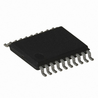
AT86RF401U-XI Atmel, AT86RF401U-XI Datasheet - Page 37

AT86RF401U-XI
Manufacturer Part Number
AT86RF401U-XI
Description
IC MICRO TX RF W/AVR 20-TSSOP
Manufacturer
Atmel
Datasheet
1.AT86RF401U-6GS.pdf
(52 pages)
Specifications of AT86RF401U-XI
Frequency
264MHz ~ 456MHz
Applications
Garage Opener, RKE, Telemetry
Modulation Or Protocol
ASK, OOK
Data Rate - Maximum
10 kbps
Power - Output
6dBm
Current - Transmitting
23.2mA
Data Interface
PCB, Surface Mount
Antenna Connector
PCB, Surface Mount
Memory Size
2KB Flash, 128 Byte EEPROM, 128Byte SRAM
Voltage - Supply
2 V ~ 5 V
Operating Temperature
-40°C ~ 85°C
Package / Case
20-TSSOP
Lead Free Status / RoHS Status
Contains lead / RoHS non-compliant
Features
-
Other names
AT86RF401U
Bit Timer Register Descriptions
Bit Timer Count Register – BTCNT
Bit Timer Control Register – BTCR
1424F–RKE–12/03
Initial Value
Initial Value
Read/Write
Read/Write
$20
$21
Bit
Bit
R/W
R/W
C7
C9
7
0
7
0
• Bit [7:0]
Lowest 8 bits of countval. When combined with bits [7:6] of the BTCR register, countval
determines a counter value that sets the width of a mark or a space that is sent to the
transmitter. The width of the mark or space is:
where P
that is determined by the ACS bits of the AVR configuration register, AVR_CONFIG.
• Bit[7:6]
Count_val[9:8]. MSB of BTCNT counter value bits.
• Bits[5:4]
Table 16. Bit Timer Mode.
• Bit[3]: Interrupts Enabled
If this bit is set, the Flag2 and Flag0 will generate their respective interrupts when they
are set. Flag0 interrupt vector is located at 0 x 04. Flag2 interrupt vector is located at
0 x 02. Typically, a JMP instruction resides at these vector locations to pass control to
an interrupt handler. For Flag0 only, slightly faster execution can be achieved if the JMP
instruction is eliminated, and the interrupt service routine is located beginning at 0 x 04.
R/W
R/W
C6
C8
6
0
6
0
P
XX
= P
XX
Mode[1:0]
is the period of the mark or space, and P
AVR
00
01
10
11
R/W
R/W
* (countval +1)
C5
M1
5
0
5
0
R/W
R/W
C4
M0
4
0
4
0
Bit Timer Function
Bit Timer Disabled
Bit Timer in Generic Timer/Counter Mode
Bit Timer in Receive Mode
Bit Timer in Transmit Mode
R/W
R/W
C3
IE
3
0
3
0
AVR
R/W
C2
F2
R
2
0
2
0
is the period of the AVR clock
AT86RF401
DATA
R/W
R/W
C1
1
0
1
0
R/W
C0
F0
0
0
R
0
0
37


