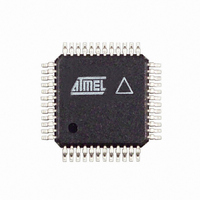
AT86RF211SAH-R Atmel, AT86RF211SAH-R Datasheet - Page 35

AT86RF211SAH-R
Manufacturer Part Number
AT86RF211SAH-R
Description
IC RF TXRX FSK 400-950MHZ 48TQFP
Manufacturer
Atmel
Datasheet
1.AT86RF211SDK.pdf
(66 pages)
Specifications of AT86RF211SAH-R
Frequency
400MHz ~ 950MHz
Data Rate - Maximum
100kbps
Modulation Or Protocol
FSK
Applications
ISM
Power - Output
7dBm ~ 12dBm
Sensitivity
-107dBm
Voltage - Supply
2.4 V ~ 3.6 V
Data Interface
PCB, Surface Mount
Antenna Connector
PCB, Surface Mount
Operating Temperature
-40°C ~ 85°C
Package / Case
48-TQFP Exposed Pad, 48-eTQFP, 48-HTQFP, 48-VQFP
Lead Free Status / RoHS Status
Contains lead / RoHS non-compliant
Memory Size
-
Current - Transmitting
-
Current - Receiving
-
2.5.1.2
Figure 2-28. Write Chronogram: Complete Write Cycle in a 10-bit Register
Figure 2-29. Write Chronogram: Partial Write Cycle, Writing 2 bits
5348B–WIRE–03/06
S D A T A
S L E
S C K
WRITE Mode (R/W = 1)
A[3]
S L E
S C K
S D A T A
A[2]
The address, R/W and data bits are clocked on the rising edge of SCK.
If the number of data bits is lower than the register capacity, the LSB bits retain their
former value, allowing a safe partial write. If the number of data bits is greater than the
register capacity, the extra bits are ignored.
The data is actually written into the register on the rising edge of SLE when the data
length is less or equal to the register length.
When trying to write more data than the register length, a data field is written on the first
extra rising clock edge of the register length.
Note:
The complete 10-bit register is updated on a rising edge of SLE.
Only the 2 MSBs are updated on the rising edge of SLE; other register bits remain
unchanged.
A[1]
A[0]
The SCK signal must be at a logic level 0 when SLE toggles up or down.
A[3]
R / W
A[2]
D[9]
A[1]
D[8]
A[0]
D[7]
R / W
D[6]
D[31]
D[5]
D[30]
D[4]
D[3]
D[2]
D[1]
AT86RF211S
D[0]
35


