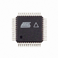
AT86RF211SAH-R Atmel, AT86RF211SAH-R Datasheet - Page 21

AT86RF211SAH-R
Manufacturer Part Number
AT86RF211SAH-R
Description
IC RF TXRX FSK 400-950MHZ 48TQFP
Manufacturer
Atmel
Datasheet
1.AT86RF211SDK.pdf
(66 pages)
Specifications of AT86RF211SAH-R
Frequency
400MHz ~ 950MHz
Data Rate - Maximum
100kbps
Modulation Or Protocol
FSK
Applications
ISM
Power - Output
7dBm ~ 12dBm
Sensitivity
-107dBm
Voltage - Supply
2.4 V ~ 3.6 V
Data Interface
PCB, Surface Mount
Antenna Connector
PCB, Surface Mount
Operating Temperature
-40°C ~ 85°C
Package / Case
48-TQFP Exposed Pad, 48-eTQFP, 48-HTQFP, 48-VQFP
Lead Free Status / RoHS Status
Contains lead / RoHS non-compliant
Memory Size
-
Current - Transmitting
-
Current - Receiving
-
Table 2-4.
Note:
5348B–WIRE–03/06
Name
NDB
SDB
MDB
WDB
Please refer to the Application Note
Discriminator Bandwidth Selection
Applicable
Mode
RF211
RF211S
RF211
RF211S
RF211S
RF211S
Figure 2-16. FSK Demodulator Schematic
The oscillator’s natural frequency is F
The signal at the oscillator’s output (point A in Figure 2-16) is proportional to the fre-
quency difference between Fin and F
a pulse duty cycle (point B). Thereafter, by low-pass filtering of the signal, a mean volt-
age of the signal is obtained (point C).
This demodulation’s architecture is thereby analog and as the output voltage is propor-
tional to the input frequency, enables transmission of a continuous stream of data of the
same value. It is not therefore mandatory to use Manchester encoding; the first bit is
correctly demodulated.
The oscillator’s feedback resistor controls the center frequency F
ing to the output of a dummy FSK demodulator driven by a 455 kHz internal reference
frequency, which is a division of the reference crystal. The discrete components con-
nected to pin 32 DISCFILT constitute the loop filter of the PLL stabilizing the 455 kHz
signal.
The input RBW resistor controls the discriminator bandwidth. Table 5 outlines some
possible choices:
Maximum FSK
Deviation (kHz)
±25 kHz
±50 kHz
±75 kHz
±125 kHz
"“Data Demodulation and Crystal Selection for the AT86RF211S”
Fin
RBW
Conversion
Gain at 2.4V
(mV/kHz)
28
14
9
5
F D
Conversion
Gain at 3V
(mV/kHz)
34
17
11
6.5
Oscillator
D
. The XOR function translates the difference into
D
and it actually oscillates at the Fin frequency.
FSKBW = 0
FSKBW = 1
Bit Configuration
DISCRANGE = 11
DISCRANGE = 10
DISCRANGE = 01
DISCRANGE = 00
A
AT86RF211S
D
, reference 5418A.
. It is adjusted accord-
B
Comment
Compatible with
AT86RF211
AT86RF211S only
C
21


