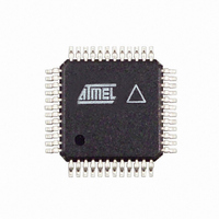
AT86RF211SAH-R Atmel, AT86RF211SAH-R Datasheet - Page 3

AT86RF211SAH-R
Manufacturer Part Number
AT86RF211SAH-R
Description
IC RF TXRX FSK 400-950MHZ 48TQFP
Manufacturer
Atmel
Datasheet
1.AT86RF211SDK.pdf
(66 pages)
Specifications of AT86RF211SAH-R
Frequency
400MHz ~ 950MHz
Data Rate - Maximum
100kbps
Modulation Or Protocol
FSK
Applications
ISM
Power - Output
7dBm ~ 12dBm
Sensitivity
-107dBm
Voltage - Supply
2.4 V ~ 3.6 V
Data Interface
PCB, Surface Mount
Antenna Connector
PCB, Surface Mount
Operating Temperature
-40°C ~ 85°C
Package / Case
48-TQFP Exposed Pad, 48-eTQFP, 48-HTQFP, 48-VQFP
Lead Free Status / RoHS Status
Contains lead / RoHS non-compliant
Memory Size
-
Current - Transmitting
-
Current - Receiving
-
1.1.5
1.1.6
1.2
1.2.1
1.2.2
1.3
5348B–WIRE–03/06
Low-power Standby Modes
Asynchronous Transparent Transmit Mode
Digital Signal Output DIGOUT
Charge and Hold Data Slicer Mode
PDN Mode
XTAL Running
Pin 17 was previously reserved and not connected, but can now deliver several signals:
After a charge phase, the comparison threshold of the data slicer is stored in the exter-
nal SKFILT capacitor. This is an additional and very easy way to implement a
transparent NRZ UART mode, for instance.
This is a very low power mode. Only the control interface is powered and I
500 nA typical.
The XTO remains active for short start-up-time applications at 150 µA, rising to 950 µA
typical if the 10.245 MHz signal is buffered on the DIGOUT pin, assuming that the load
is 10 pF.
The chip is set-up by the MCU to act as transmitter. It then acts like a pipe in which any
data entering DATAMSG is immediately radiated on the antenna. No data is stored or
processed on the chip. The transmission is asynchronous.
• Divided XTAL reference clock
• Carrier detection when RSSI is above predefined TRSSI
• XTO running flag
• 455 kHz signal from the discriminator PLL
• Receive mode flag
• 1 kHz reference clock of the wake-up timer
• Lock detect flag PLLL of the main PLL
AT86RF211S
CC
is as low as
3


