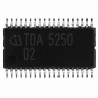
TDA5250 Infineon Technologies, TDA5250 Datasheet - Page 20

TDA5250
Manufacturer Part Number
TDA5250
Description
TX/RX ASK/FSK 868-870MHZ 38TSSOP
Manufacturer
Infineon Technologies
Type
Transceiverr
Specifications of TDA5250
Package / Case
38-TSSOP
Frequency
868MHz
Data Rate - Maximum
64kbps
Modulation Or Protocol
ASK, FSK
Applications
RKE, Remote Control Systems
Power - Output
9dBm
Sensitivity
-109dBm
Voltage - Supply
2.1 V ~ 5.5 V
Current - Receiving
9mA
Current - Transmitting
12mA
Data Interface
PCB, Surface Mount
Antenna Connector
PCB, Surface Mount
Operating Temperature
-40°C ~ 85°C
Operating Frequency
870 MHz
Operating Supply Voltage
2.5 V, 3.3 V, 5 V
Maximum Operating Temperature
+ 85 C
Minimum Operating Temperature
- 40 C
Mounting Style
SMD/SMT
Operating Temperature (min)
-40C
Operating Temperature (max)
85C
Operating Temperature Classification
Industrial
Product Depth (mm)
4.4mm
Product Length (mm)
9.7mm
Operating Supply Voltage (min)
2.1V
Operating Supply Voltage (max)
5.5V
Lead Free Status / RoHS Status
Lead free / RoHS Compliant
Memory Size
-
Lead Free Status / Rohs Status
Compliant
Other names
SP000012956
TDA5250
TDA5250INTR
TDA5250XT
TDA5250XT
TDA5250
TDA5250INTR
TDA5250XT
TDA5250XT
Available stocks
Company
Part Number
Manufacturer
Quantity
Price
Company:
Part Number:
TDA5250
Manufacturer:
Infineon Technologies
Quantity:
135
Company:
Part Number:
TDA5250D2
Manufacturer:
INFINEON
Quantity:
300
Part Number:
TDA5250D2
Manufacturer:
INFINEON/英飞凌
Quantity:
20 000
2.4.5
The Phase Locked Loop synthesizer consists of two VCOs (i.e. transmit and receive VCO), a
divider by 4, an asynchronous divider chain with selectable overall division ratio, a phase detector
with charge pump and a loop filter and is fully implemented on-chip. The VCOs are including spiral
inductors and varactor diodes. The center frequency of the transmit VCO is 868MHz, the center
frequency of the receive VCO is 1156MHz.
Generally in receive mode the relationship between local oscillator frequency f osc , the receive RF
frequency f RF and the IF frequency f IF and thus the frequency that is applied to the I/Q Mixers is
given in the following formula:
f osc = 4/3 f RF = 4 f IF
The VCO signal is applied to a divider by 4 which is producing approximately 289MHz signals in
quadrature. The overall division ratio of the divider chain following the divider by 4 is 12 in transmit
mode and 16 in receive mode as the nominal crystal oscillator frequency is 18.083MHz. The
division ratio is controlled by the RxTx pin (pin 5) and the D10 bit in the CONFIG register.
2.4.6
The I/Q IF to zero-IF mixers are followed by baseband 6
RF-channel filtering.
Figure 2-3
The bandwidth of the filters is controlled by the values set in the filter-register. It can be adjusted
between 50 and 350kHz in 50kHz steps via the bits D1 to D3 of the LPF register (subaddress 03H).
2.4.7
The I/Q Limiters are DC coupled multistage amplifiers with offset-compensating feedback circuit
and an overall gain of approximately 80dB each in the frequency range of 100Hz up to 350kHz.
Receive Signal Strength Indicator (RSSI) generators are included in both limiters which produce DC
voltages that are directly proportional to the input signal level in the respective channels. The
resulting I- and Q-channel RSSI-signals are summed to the nominal RSSI signal.
Data Sheet
PLL Synthesizer
I/Q Filters
I/Q Limiters
One I/Q Filter stage
INTERNAL BUS
20
OP
th
order low pass filters that are used for
Functional Description
[2 – 1]
TDA5250 D2
Version 1.7
2007-02-26
iq_filter.wmf


