CSM56F801SLK Freescale Semiconductor, CSM56F801SLK Datasheet
CSM56F801SLK
Specifications of CSM56F801SLK


Related parts for CSM56F801SLK

CSM56F801SLK Summary of contents
Page 1
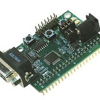
... Freescale Semiconductor Development Module for Freescale DSP56F801 © Freescale Semiconductor, Inc., 2004. All rights reserved. CSM-56F801 ...
Page 2
... BILL OF MATERIALS .......................................................................................................... 13 Figure 1: PWR_SEL Jumper Settings.........................................................................................8 Figure 2: COM Connector........................................................................................................10 Figure 3: JTAG / OnCE BDM Connection.................................................................................11 Figure 4: MCU I/O Connector ...................................................................................................11 Table 1: Program Memory Map ..................................................................................................6 Table 2: Data Memory Map ........................................................................................................7 Table 3: COM Signal Connections ............................................................................................9 Table 4: User Option Jumper Settings......................................................................................10 CONTENTS FIGURES TABLES 2 Freescale Semiconductor, Inc ...
Page 3
... Cut-Trace – a circuit trace connection between component pads. The circuit trace may be cut using a razor knife to break the default connection. To reconnect the circuit, simply install a suitably sized 0-ohm resistor or attach a wire across the pads. REVISION Rev C Updated format and revision 3 Freescale Semiconductor, Inc Comments ...
Page 4
... Barrel Connector Power Input • JTAG Connector • DB9 Communications Connector • Supplied with DB9 Serial Cable, Documentation (CD), Manual, and Wall plug type power supply. Specifications: Module Size 2.2” x 1.6” Power Input: +9VDC @ 200 mA typical +16VDC range 4 Freescale Semiconductor, Inc ...
Page 5
... Reference documents are provided on the support CD in Acrobat Reader format. CSM56F801_SCH_B.pdf CSM56F801_UG.pdf DSP56F801-7UM.pdf DPSP56F801.pdf DSOP56F800.pdf AN1909.pdf CSM-56F801 Module Schematic Rev B CSM-56F801 User Guide (this document) DSP56F80x Users Manual Technical Data Sheet DSOP56F800 Family Manual Multiple Target Features Using CodeWarrior 5 Freescale Semiconductor, Inc ...
Page 6
... NOTE: The first 4 logical addresses are a reflection of the first 4 physical addresses of Boot Flash Program Memory – Mode 0A Boot Flash Program Flash Reserved Program RAM Boot Flash Reserved 6 Freescale Semiconductor, Inc ...
Page 7
... Care should be exercised not to over-drive this input. This connection may also be used to power external modules attached to connector J1. The PWR_SEL option header determines how power is routed to the module Data RAM Reserved Peripherals Data Flash Reserved Core Registers 7 Freescale Semiconductor, Inc ...
Page 8
... The system consists of a POR circuit and a low-voltage interrupt (LVI) circuit. reaches an acceptable level. The LVI provides an interrupt out when voltage falls below the trip level. Refer to the MPU User Guide for further details. The POR circuit holds the MPU in reset until voltage 8 Freescale Semiconductor, Inc The ...
Page 9
... A standard 9-pin Dsub connector provides external connections for the COM port. The COM port is used by default with the debug monitor. Component U2 provides RS-232 translation services. The figure below details the DB9 connector. MPU Port Connector J1 GPIOB0/TXD0 5 GPIOB1/RXD0 7 9 Freescale Semiconductor, Inc Signal Disable CT4 CT4 ...
Page 10
... Flow control is provided at test points on the module. Pins 1, 4, and 6 are connected together. On Off Enable SW1 Disable SW1 Enable SW2 Disable SW2 Enable LED1 Disable LED1 Enable LED2 Disable LED2 10 Freescale Semiconductor, Inc MPU Signal PWMA0 PWMA1 TD0 TD1 ...
Page 11
... N/C (key) 8 TMS /TRST 2 IREQA* 4 RESET Note: Default signal assignment should be disabled to use the signal at connector J1 11 Freescale Semiconductor, Inc Default Signal Assignment MCU Port Signal Disable TxD0 COM1 TXD CT-4 RxD0 COM1 RXD CT-5 TD0 SW1 User1 TD1 SW2 User2 ...
Page 12
... APPENDIX A Mechanical Details 12 Freescale Semiconductor, Inc ...
Page 13
... P.O. Box 5405 Denver, Colorado 80217 1-800-441-2447 or 303-675-2140 Fax: 303-675-2150 LDCForFreescaleSemiconductor@hibbertgroup.com Document Number: CSM56F801SLKUG Rev. 0, Draft A 07/2006 Information in this document is provided solely to enable system and software implementers to use Freescale Semiconductor products. There are no express or implied copyright licenses granted hereunder to design or fabricate any integrated circuits or integrated circuits based on the information in this document ...