AD6655-150EBZ Analog Devices Inc, AD6655-150EBZ Datasheet - Page 43
AD6655-150EBZ
Manufacturer Part Number
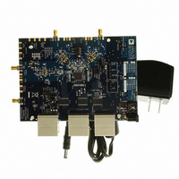
AD6655-150EBZ
Description
BOARD EVAL FOR 150MSPS AD6655
Manufacturer
Analog Devices Inc
Type
Receiverr
Datasheet
1.AD6655-125EBZ.pdf
(88 pages)
Specifications of AD6655-150EBZ
Frequency
0Hz ~ 450MHz
Silicon Manufacturer
Analog Devices
Application Sub Type
IF Diversity Receiver
Kit Application Type
Communication & Networking
Silicon Core Number
AD6655
Kit Contents
Evaluation Board With AD6655 And Software
Lead Free Status / RoHS Status
Lead free / RoHS Compliant
For Use With/related Products
AD6655
Lead Free Status / RoHS Status
Lead free / RoHS Compliant, Lead free / RoHS Compliant


Increment Gain (IG) and Decrement Gain (DG)
The increment gain and decrement gain indicators are intended
to be used together to provide information to enable external
gain control. The decrement gain indicator works in conjunction
with the coarse upper threshold bits, asserting when the input
magnitude is greater than the 3-bit value in the coarse upper
threshold register (Address 0x105). The increment gain indicator,
similarly, corresponds to the fine lower threshold bits except
that it is asserted only if the input magnitude is less than the
value programmed in the fine lower threshold register after the
dwell time elapses. The dwell time is set by the 16-bit dwell time
value located at Address 0x10A and Address 0x10B and is set in
units of ADC input clock cycles ranging from 1 to 65,535. The
fine lower threshold register is a 13-bit register that is compared
IG
C_UT OR F_UT*
F_LT
DG
*C_UT AND F_UT DIFFER ONLY IN ACCURACY AND LATENCY.
NOTE: OUTPUTS FOLLOW THE INSTANTEOUS SIGNAL LEVEL AND NOT THE ENVELOPE BUT ARE GUARANTEED ACTIVE FOR A MINIMUM OF 2 ADC CLOCK CYCLES.
Figure 75. Threshold Settings for C_UT, F_UT, F_LT, DG, and IG
RISE ABOVE F_LT
TIMER RESET BY
Rev. A | Page 43 of 88
DWELL TIME
with the magnitude at the output of the ADC. This comparison
is subject to the ADC clock latency but allows a finer, more
accurate comparison. The fine upper threshold magnitude is
defined by the following equation:
The decrement gain output works from the ADC fast detect
output pins, providing a fast indication of potential overrange
conditions. The increment gain uses the comparison at the
output of the ADC, requiring the input magnitude to remain
below an accurate, programmable level for a predefined period
before signaling external circuitry to increase the gain.
The operation of the increment gain output and decrement gain
output is shown graphically in Figure 75.
dBFS = 20 log(Threshold Magnitude/2
UPPER THRESHOLD (COARSE OR FINE)
DWELL TIME
FINE LOWER THRESHOLD
TIMER COMPLETES BEFORE
SIGNAL RISES ABOVE F_LT
13
)
AD6655
Related parts for AD6655-150EBZ
Image
Part Number
Description
Manufacturer
Datasheet
Request
R

Part Number:
Description:
BOARD EVAL W/AD6655 & SOFTWARE
Manufacturer:
Analog Devices Inc
Datasheet:

Part Number:
Description:
±1.7g Dual-Axis IMEMS Accelerometer Evaluation Board
Manufacturer:
Analog Devices Inc
Datasheet:

Part Number:
Description:
Inertial Sensor Evaluation System
Manufacturer:
Analog Devices Inc
Datasheet:
Part Number:
Description:
Manufacturer:
Analog Devices Inc
Datasheet:
Part Number:
Description:
Manufacturer:
Analog Devices Inc
Datasheet:
Part Number:
Description:
Manufacturer:
Analog Devices Inc
Datasheet:
Part Number:
Description:
Manufacturer:
Analog Devices Inc
Datasheet:
Part Number:
Description:
Manufacturer:
Analog Devices Inc
Datasheet:
Part Number:
Description:
Manufacturer:
Analog Devices Inc
Datasheet:
Part Number:
Description:
Manufacturer:
Analog Devices Inc
Datasheet:
Part Number:
Description:
Manufacturer:
Analog Devices Inc
Datasheet:
Part Number:
Description:
Manufacturer:
Analog Devices Inc
Datasheet:
Part Number:
Description:
Manufacturer:
Analog Devices Inc
Datasheet: