AD6655-150EBZ Analog Devices Inc, AD6655-150EBZ Datasheet - Page 35
AD6655-150EBZ
Manufacturer Part Number
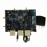
AD6655-150EBZ
Description
BOARD EVAL FOR 150MSPS AD6655
Manufacturer
Analog Devices Inc
Type
Receiverr
Datasheet
1.AD6655-125EBZ.pdf
(88 pages)
Specifications of AD6655-150EBZ
Frequency
0Hz ~ 450MHz
Silicon Manufacturer
Analog Devices
Application Sub Type
IF Diversity Receiver
Kit Application Type
Communication & Networking
Silicon Core Number
AD6655
Kit Contents
Evaluation Board With AD6655 And Software
Lead Free Status / RoHS Status
Lead free / RoHS Compliant
For Use With/related Products
AD6655
Lead Free Status / RoHS Status
Lead free / RoHS Compliant, Lead free / RoHS Compliant


By asserting PDWN (either through the SPI port or by asserting
the PDWN pin high), the AD6655 is placed in power-down
mode. In this state, the ADC typically dissipates 2.5 mW.
During power-down, the output drivers are placed in a high
impedance state. Asserting the PDWN pin low returns the
AD6655 to its normal operating mode. Note that PDWN is
referenced to the digital output driver supply (DRVDD) and
should not exceed that supply voltage. PDWN can be driven
with 1.8 V logic, even when DRVDD is at 3.3 V.
Low power dissipation in power-down mode is achieved by
shutting down the reference, reference buffer, biasing networks,
and clock. Internal capacitors are discharged when entering
power-down mode and then must be recharged when returning
to normal operation. As a result, wake-up time is related to the
time spent in power-down mode, and shorter power-down
cycles result in proportionally shorter wake-up times.
When using the SPI port interface, the user can place the ADC
in power-down mode or standby mode. Standby mode allows
the user to keep the internal reference circuitry powered when
faster wake-up times are required. See the Memory Map Register
Description section and Application Note AN-877, Interfacing
to High Speed ADCs via SPI at
details.
DIGITAL OUTPUTS
The AD6655 output drivers can be configured to interface with
1.8 V to 3.3 V CMOS logic families by matching DRVDD to the
digital supply of the interfaced logic. Alternatively, the AD6655
outputs can be configured for either ANSI LVDS or reduced
drive LVDS using a 1.8 V DRVDD supply.
In CMOS output mode, the output drivers are sized to provide
sufficient output current to drive a wide variety of logic families.
However, large drive currents tend to cause current glitches on
the supplies that may affect converter performance. Applica-
1.00
0.75
0.50
0.25
0
0
Figure 67. AD6655-80 Power and Current vs. Sample Rate
IAVDD
20
SAMPLE RATE (MSPS)
40
www.analog.com
TOTAL POWER
IDVDD
IDRVDD
60
for additional
80
0.4
0.3
0.2
0.1
0
Rev. A | Page 35 of 88
tions requiring the ADC to drive large capacitive loads or large
fanouts may require external buffers or latches.
The output data format can be selected for either offset binary
or twos complement by setting the SCLK/DFS pin when operating
in the external pin mode (see Table 16). As detailed in
Application Note AN-877, Interfacing to High Speed ADCs via
SPI, the data format can be selected for offset binary, twos
complement, or gray code when using the SPI control.
Table 16. SCLK/DFS Mode Selection (External Pin Mode)
Voltage at Pin
AGND (default)
AVDD
Digital Output Enable Function (OEB)
The AD6655 has a flexible three-state ability for the digital output
pins. The three-state mode is enabled using the SMI SDO/OEB pin
or through the SPI interface. If the SMI SDO/OEB pin is low, the
output data drivers are enabled. If the SMI SDO/OEB pin is high,
the output data drivers are placed in a high impedance state.
This OEB function is not intended for rapid access to the data
bus. Note that OEB is referenced to the digital output driver
supply (DRVDD) and should not exceed that supply voltage.
OEB can be driven with 1.8 V logic even when DRVDD is at 3.3 V.
When using the SPI interface, the data and fast detect outputs of
each channel can be independently three-stated by using the
output enable bar bit (Bit 4) in Register 0x14.
Interleaved CMOS Mode
Setting Bit 5 in Register 0x14 enables interleaved CMOS output
mode. In this mode, output data is routed through Port A with
the ADC Channel A output data present on the rising edge of
DCO and the ADC Channel B output data present on the
falling edge of DCO.
Timing
The AD6655 provides latched data with a pipeline delay that is
dependent on which of the digital back end features are enabled.
Data outputs are available one propagation delay (t
rising edge of the clock signal.
The length of the output data lines and loads placed on them
should be minimized to reduce transients within the AD6655.
These transients can degrade converter dynamic performance.
The lowest typical conversion rate of the AD6655 is 10 MSPS. At
clock rates below 10 MSPS, dynamic performance may degrade.
Data Clock Output (DCO)
The AD6655 also provides data clock output (DCO) intended for
capturing the data in an external register. Figure 2 through Figure 6
show a graphical timing description of the AD6655 output modes.
SCLK/DFS
Offset binary
Twos complement
SDIO/DCS
DCS disabled
DCS enabled
PD
AD6655
) after the
Related parts for AD6655-150EBZ
Image
Part Number
Description
Manufacturer
Datasheet
Request
R

Part Number:
Description:
BOARD EVAL W/AD6655 & SOFTWARE
Manufacturer:
Analog Devices Inc
Datasheet:

Part Number:
Description:
±1.7g Dual-Axis IMEMS Accelerometer Evaluation Board
Manufacturer:
Analog Devices Inc
Datasheet:

Part Number:
Description:
Inertial Sensor Evaluation System
Manufacturer:
Analog Devices Inc
Datasheet:
Part Number:
Description:
Manufacturer:
Analog Devices Inc
Datasheet:
Part Number:
Description:
Manufacturer:
Analog Devices Inc
Datasheet:
Part Number:
Description:
Manufacturer:
Analog Devices Inc
Datasheet:
Part Number:
Description:
Manufacturer:
Analog Devices Inc
Datasheet:
Part Number:
Description:
Manufacturer:
Analog Devices Inc
Datasheet:
Part Number:
Description:
Manufacturer:
Analog Devices Inc
Datasheet:
Part Number:
Description:
Manufacturer:
Analog Devices Inc
Datasheet:
Part Number:
Description:
Manufacturer:
Analog Devices Inc
Datasheet:
Part Number:
Description:
Manufacturer:
Analog Devices Inc
Datasheet:
Part Number:
Description:
Manufacturer:
Analog Devices Inc
Datasheet: