XR21V1414IM48-F Exar Corporation, XR21V1414IM48-F Datasheet - Page 7
XR21V1414IM48-F
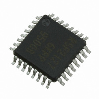
Manufacturer Part Number
XR21V1414IM48-F
Description
IC UART FIFO USB QUAD 48TQFP
Manufacturer
Exar Corporation
Type
USB UARTsr
Datasheet
1.XR21V1414IM48-F.pdf
(32 pages)
Specifications of XR21V1414IM48-F
Package / Case
48-TQFP
Features
*
Number Of Channels
1, UART
Fifo's
128 Byte
Protocol
USB 2.0
Voltage - Supply
3.3V
With Auto Flow Control
Yes
Mounting Type
Surface Mount
Maximum Operating Temperature
+ 85 C
Minimum Operating Temperature
- 40 C
Mounting Style
SMD/SMT
Supply Current
16 mA
Operating Supply Voltage
2.97 V to 3.63 V
No. Of Channels
4
Data Rate
12Mbps
Uart Features
Automatic Hardware And Software Flow Control, Half-Duplex Mode, Fractional Baud Rate Generator
Supply Voltage Range
2.97V To 3.63V
Rohs Compliant
Yes
Lead Free Status / RoHS Status
Lead free / RoHS Compliant
For Use With
1016-1303 - EVAL BOARD FOR XR21V1414IM
Lead Free Status / Rohs Status
Lead free / RoHS Compliant
Other names
1016-1304
Available stocks
Company
Part Number
Manufacturer
Quantity
Price
Company:

Part Number:
XR21V1414IM48-F
Manufacturer:
EXAR
Quantity:
5 000
Company:
Part Number:
XR21V1414IM48-F
Manufacturer:
Exar Corporation
Quantity:
10 000
Part Number:
XR21V1414IM48-F
Manufacturer:
EXAR/艾科嘉
Quantity:
20 000


REV. 1.1.0
Pin Description
USB Interface Signals
I2C Interface Signals
GPIOD2/DSRD#
GPIOD3/DTRD#
GPIOD4/CTSD#
GPIOD5/RTSD#
USBD+
USBD-
N
SDA
SCL
AME
48-QFN
P
48
47
46
43
42
35
36
IN
3
#
T
OD
I/O
I/O
I/O
I/O
I/O
I/O
YPE
I
UART Channel D general purpose I/O or UART Data-Set-Ready input
(active low).
Flow Control” on page 13.
which is disabled during suspend mode. If using this GPIO as an input, an
external pull-up resistor is required to minimize the power consumption in
the suspend mode.
UART Channel D general purpose I/O or UART Data-Terminal-Ready out-
put (active low).
ware Flow Control” on page 13.
resistor which is disabled during suspend mode. If using this GPIO as an
input, an external pull-up resistor is required to minimize the power con-
sumption in the suspend mode.
UART Channel D general purpose I/O or UART Clear-to-Send input
(active low).
Flow Control” on page 12.
which is disabled during suspend mode. If using this GPIO as an input, an
external pull-up resistor is required to minimize the power consumption in
the suspend mode.
UART Channel D general purpose I/O or UART Request-to-Send output
(active low).
Flow Control” on page 12.
which is disabled during suspend mode. If using this GPIO as an input, an
external pull-up resistor is required to minimize the power consumption in
the suspend mode.
USB port differential data plus. This pin has a 1.5 K Ohm internal pull-up
resistor.
USB port differential data minus.
I
EEPROM can be used to store default configurations upon power-up
including the USB Vendor ID and Device ID. See
resisitor (typically 4.7 to 10 KOhms) is required.
If an EEPROM is not used, this pin can be used with the SCL pin to select
the Remote Wake-up and Power modes. An external pull-up or pull-down
resistor is required. See
I
used to store default configurations upon power-up including the USB
Vendor ID and Device ID. See
to 10 KOhms) is required.
If an EEPROM is not used, this pin can be used with the SDA pin to select
the Remote Wake-up and Power modes. An external pull-up or pull-down
resistor is required. See
2
2
C-controller data input/output (open-drain). An optional external I
C-controller serial input clock. An optional external I
7
See ”Section 1.5.5, Automatic DTR/DSR Hardware
See ”Section 1.5.4, Automatic RTS/CTS Hardware
See ”Section 1.5.4, Automatic RTS/CTS Hardware
See ”Section 1.5.5, Automatic DTR/DSR Hard-
Table 2
Table 2
D
Table 3
ESCRIPTION
This pin has an internal pull-up resistor
This pin has an internal pull-up resistor
This pin has an internal pull-up resistor
.
.
4-CH FULL-SPEED USB UART
This pin has an internal pull-up
. A pull-up resisitor (typically 4.7
Table 3
2
C EEPROM can be
XR21V1414
. A pull-up
2
C
Related parts for XR21V1414IM48-F
Image
Part Number
Description
Manufacturer
Datasheet
Request
R

Part Number:
Description:
4-ch Full-speed Usb Uart
Manufacturer:
Exar Corporation
Datasheet:
Part Number:
Description:
BiCMOS Fixed, Quad, Voltage Output, Single or Dual Supply 8-Bit Digital-to-Analog Converter
Manufacturer:
Exar Corporation
Datasheet:
Part Number:
Description:
Manufacturer:
Exar Corporation
Datasheet:
Part Number:
Description:
Voltage-Controlled Oscillator
Manufacturer:
Exar Corporation
Datasheet:
Part Number:
Description:
INTEGRATED LINE TRANSMITTER
Manufacturer:
Exar Corporation
Datasheet:
Part Number:
Description:
Monolithic Function Generator
Manufacturer:
Exar Corporation
Datasheet:
Part Number:
Description:
CMOS Microprocessor Compatible Double-Buffered 12-Bit Digital-to-Analog Converter
Manufacturer:
Exar Corporation
Datasheet:
Part Number:
Description:
CMOS 6 BIT HIGH SPEED ANALOG TO DIGITAL CONVERTER
Manufacturer:
Exar Corporation
Datasheet:
Part Number:
Description:
Manufacturer:
Exar Corporation
Datasheet:
Part Number:
Description:
Manufacturer:
Exar Corporation
Datasheet:
Part Number:
Description:
8-Channel, Voltage Output 10 MHz Input Bandwidth 8-Bit Multiplying DACs with Serial Digital Data Por
Manufacturer:
Exar Corporation
Datasheet:
Part Number:
Description:
15 V CMOS Multiplying10-Bit Digital-to-Analog Converter
Manufacturer:
Exar Corporation
Datasheet:
Part Number:
Description:
Monolithic Function Generator
Manufacturer:
Exar Corporation
Datasheet: