XR21V1414IM48-F Exar Corporation, XR21V1414IM48-F Datasheet - Page 23
XR21V1414IM48-F
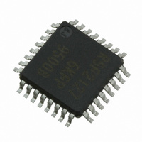
Manufacturer Part Number
XR21V1414IM48-F
Description
IC UART FIFO USB QUAD 48TQFP
Manufacturer
Exar Corporation
Type
USB UARTsr
Datasheet
1.XR21V1414IM48-F.pdf
(32 pages)
Specifications of XR21V1414IM48-F
Package / Case
48-TQFP
Features
*
Number Of Channels
1, UART
Fifo's
128 Byte
Protocol
USB 2.0
Voltage - Supply
3.3V
With Auto Flow Control
Yes
Mounting Type
Surface Mount
Maximum Operating Temperature
+ 85 C
Minimum Operating Temperature
- 40 C
Mounting Style
SMD/SMT
Supply Current
16 mA
Operating Supply Voltage
2.97 V to 3.63 V
No. Of Channels
4
Data Rate
12Mbps
Uart Features
Automatic Hardware And Software Flow Control, Half-Duplex Mode, Fractional Baud Rate Generator
Supply Voltage Range
2.97V To 3.63V
Rohs Compliant
Yes
Lead Free Status / RoHS Status
Lead free / RoHS Compliant
For Use With
1016-1303 - EVAL BOARD FOR XR21V1414IM
Lead Free Status / Rohs Status
Lead free / RoHS Compliant
Other names
1016-1304
Available stocks
Company
Part Number
Manufacturer
Quantity
Price
Company:

Part Number:
XR21V1414IM48-F
Manufacturer:
EXAR
Quantity:
5 000
Company:
Part Number:
XR21V1414IM48-F
Manufacturer:
Exar Corporation
Quantity:
10 000
Part Number:
XR21V1414IM48-F
Manufacturer:
EXAR/艾科嘉
Quantity:
20 000


REV. 1.1.0
FLOW_CONTROL[2:0]: Flow control mode select
FLOW_CONTROL[3]: Half-Duplex Mode
FLOW_CONTROL[7:4]: Reserved
These bits are reserved and should remain ’0’.
The XON_CHAR and XOFF_CHAR registers store the XON and XOFF characters, respectively, that are used
in the Automatic Software Flow control.
XON_CHAR[7:0]: XON Character
In Automatic Software Flow control mode, the UART will resume data transmission when the XON character
has been received.
For behavior in the Address Match mode, see
page
For behavior in the Address Match with TX Flow Control mode, see
address matching” on page
XOFF_CHAR[7:0]: XOFF Character
In Automatic Software Flow control mode, the UART will suspend data transmission when the XOFF character
has been received.
For behavior in the Address Match mode, see
page
For behavior in the Address Match with TX Flow Control mode, see
Around Delay” on page
3.3.7
Logic 0 = Normal (full-duplex) mode. The UART can transmit and receive data at the same time.
Logic 1 = Half-duplex Mode. In half-duplex mode, any data on the RX pin is ignored when the UART is
transmitting data.
13.
13.
M
ODE
0
1
2
3
4
XON_CHAR, XOFF_CHAR Register Descriptions (Read/Write)
B
IT
0
0
0
0
1
-2 B
14.
IT
0
0
1
1
0
-1 B
13.
IT
0
1
0
1
0
T
-0
ABLE
No flow control, no address matching.
HW flow control enabled. Auto RTS/CTS or DTR/DSR must be selected by
GPIO_MODE.
SW flow control enabled
Multidrop mode - RX only after address match, TX independent. (Typically
used with GPIO_MODE 3)
Multidrop mode - RX / TX only after address match. (Typically used with
GPIO_MODE 4)
13: F
LOW
“Section 1.5.7, Multidrop Mode with address matching” on
“Section 1.5.7, Multidrop Mode with address matching” on
C
ONTROL
23
M
ODE
M
ODE
S
ELECTION
D
ESCRIPTION
“Section 1.5.7, Multidrop Mode with
“Section 1.5.8, Programmable Turn-
4-CH FULL-SPEED USB UART
XR21V1414
Related parts for XR21V1414IM48-F
Image
Part Number
Description
Manufacturer
Datasheet
Request
R

Part Number:
Description:
4-ch Full-speed Usb Uart
Manufacturer:
Exar Corporation
Datasheet:
Part Number:
Description:
BiCMOS Fixed, Quad, Voltage Output, Single or Dual Supply 8-Bit Digital-to-Analog Converter
Manufacturer:
Exar Corporation
Datasheet:
Part Number:
Description:
Manufacturer:
Exar Corporation
Datasheet:
Part Number:
Description:
Voltage-Controlled Oscillator
Manufacturer:
Exar Corporation
Datasheet:
Part Number:
Description:
INTEGRATED LINE TRANSMITTER
Manufacturer:
Exar Corporation
Datasheet:
Part Number:
Description:
Monolithic Function Generator
Manufacturer:
Exar Corporation
Datasheet:
Part Number:
Description:
CMOS Microprocessor Compatible Double-Buffered 12-Bit Digital-to-Analog Converter
Manufacturer:
Exar Corporation
Datasheet:
Part Number:
Description:
CMOS 6 BIT HIGH SPEED ANALOG TO DIGITAL CONVERTER
Manufacturer:
Exar Corporation
Datasheet:
Part Number:
Description:
Manufacturer:
Exar Corporation
Datasheet:
Part Number:
Description:
Manufacturer:
Exar Corporation
Datasheet:
Part Number:
Description:
8-Channel, Voltage Output 10 MHz Input Bandwidth 8-Bit Multiplying DACs with Serial Digital Data Por
Manufacturer:
Exar Corporation
Datasheet:
Part Number:
Description:
15 V CMOS Multiplying10-Bit Digital-to-Analog Converter
Manufacturer:
Exar Corporation
Datasheet:
Part Number:
Description:
Monolithic Function Generator
Manufacturer:
Exar Corporation
Datasheet: