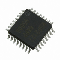
XR21V1414IM48-F Exar Corporation, XR21V1414IM48-F Datasheet - Page 28

XR21V1414IM48-F
Manufacturer Part Number
XR21V1414IM48-F
Description
IC UART FIFO USB QUAD 48TQFP
Manufacturer
Exar Corporation
Type
USB UARTsr
Datasheet
1.XR21V1414IM48-F.pdf
(32 pages)
Specifications of XR21V1414IM48-F
Package / Case
48-TQFP
Features
*
Number Of Channels
1, UART
Fifo's
128 Byte
Protocol
USB 2.0
Voltage - Supply
3.3V
With Auto Flow Control
Yes
Mounting Type
Surface Mount
Maximum Operating Temperature
+ 85 C
Minimum Operating Temperature
- 40 C
Mounting Style
SMD/SMT
Supply Current
16 mA
Operating Supply Voltage
2.97 V to 3.63 V
No. Of Channels
4
Data Rate
12Mbps
Uart Features
Automatic Hardware And Software Flow Control, Half-Duplex Mode, Fractional Baud Rate Generator
Supply Voltage Range
2.97V To 3.63V
Rohs Compliant
Yes
Lead Free Status / RoHS Status
Lead free / RoHS Compliant
For Use With
1016-1303 - EVAL BOARD FOR XR21V1414IM
Lead Free Status / Rohs Status
Lead free / RoHS Compliant
Other names
1016-1304
Available stocks
Company
Part Number
Manufacturer
Quantity
Price
Company:
Part Number:
XR21V1414IM48-F
Manufacturer:
EXAR
Quantity:
5 000
Company:
Part Number:
XR21V1414IM48-F
Manufacturer:
Exar Corporation
Quantity:
10 000
Part Number:
XR21V1414IM48-F
Manufacturer:
EXAR/艾科嘉
Quantity:
20 000
XR21V1414
4-CH FULL-SPEED USB UART
CUSTOM_INT_PACKET[6]: GPIO5
CUSTOM_INT_PACKET[7]: Reserved
This bit is reserved and should remain ’0’.
Logic 0 = Disable GPIO4 status in custom interrupt packet.
Logic 1 = Enable GPIO4 status in custom interrupt packet.
Logic 0 = Disable GPIO5 status in custom interrupt packet.
Logic 1 = Enable GPIO5 status in custom interrupt packet.
O
D15..D7
B
FFSET
D6
D5
D4
D3
D2
D1
D0
IT
0
1
2
4
6
8
(
S
)
bmRequestType
bNotification
wLength
wValue
wIndex
bRingSignal
F
bRxCarrier
bTxCarrier
Data
bOverRun
bFraming
IELD
bParity
bBreak
F
IELD
T
ABLE
(B
S
YTES
Reserved (0)
Received data has been discarded due to overrun in the device.
A parity error has occured.
A framing error has occured.
State of ring signal detection of the device.
State of break detection mechanism of the device.
State of transmission carrier. This signal corresponds to V.24 signal 106 and
RS-232 signal DSR.
State of receiver carrier detection mechanism of device. This signal corre-
sponds to V.24 signal 109 and RS-232 signal DCD.
17: D
IZE
1
1
2
2
2
2
T
ABLE
)
ATA
(See
8’b10100001
or
16: I
int_status
16’h0000
16’h0000
16’h0002
Standard
Table 18
F
V
8’h20
IELD OF
Table 17
ALUE
NTERRUPT
)
S
28
TANDARD
D6:5 = Class Type
D4-0: = Interface Recipient
D7-0 = Interface number, 8’h00 for the CDC Com-
mand Interface
D7 = Device-to-host direction
Defined encoding for SERIAL_STATE
D15-8 = Reserved (0)
2 bytes of transferred data
D15-7 = Reserved (0)
D6 = bOverRun
D5 = bParity
D4 = bFraming
D3 = bRingSignal (RI)
D2 = bBreak
D1 = bTxCarrier (DSR)
D0 = bRxCarrier (CD)
P
ACKET
D
I
NTERRUPT
ESCRIPTION
F
ORMAT
D
P
ESCRIPTION
ACKET
REV. 1.1.0


