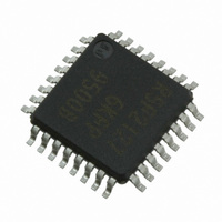
XR21V1414IM48-F Exar Corporation, XR21V1414IM48-F Datasheet - Page 22

XR21V1414IM48-F
Manufacturer Part Number
XR21V1414IM48-F
Description
IC UART FIFO USB QUAD 48TQFP
Manufacturer
Exar Corporation
Type
USB UARTsr
Datasheet
1.XR21V1414IM48-F.pdf
(32 pages)
Specifications of XR21V1414IM48-F
Package / Case
48-TQFP
Features
*
Number Of Channels
1, UART
Fifo's
128 Byte
Protocol
USB 2.0
Voltage - Supply
3.3V
With Auto Flow Control
Yes
Mounting Type
Surface Mount
Maximum Operating Temperature
+ 85 C
Minimum Operating Temperature
- 40 C
Mounting Style
SMD/SMT
Supply Current
16 mA
Operating Supply Voltage
2.97 V to 3.63 V
No. Of Channels
4
Data Rate
12Mbps
Uart Features
Automatic Hardware And Software Flow Control, Half-Duplex Mode, Fractional Baud Rate Generator
Supply Voltage Range
2.97V To 3.63V
Rohs Compliant
Yes
Lead Free Status / RoHS Status
Lead free / RoHS Compliant
For Use With
1016-1303 - EVAL BOARD FOR XR21V1414IM
Lead Free Status / Rohs Status
Lead free / RoHS Compliant
Other names
1016-1304
Available stocks
Company
Part Number
Manufacturer
Quantity
Price
Company:
Part Number:
XR21V1414IM48-F
Manufacturer:
EXAR
Quantity:
5 000
Company:
Part Number:
XR21V1414IM48-F
Manufacturer:
Exar Corporation
Quantity:
10 000
Part Number:
XR21V1414IM48-F
Manufacturer:
EXAR/艾科嘉
Quantity:
20 000
XR21V1414
4-CH FULL-SPEED USB UART
This register controls the character format such as the word length (7, 8 or 9), parity (odd, even, forced ’0’, or
forced ’1’) and number of stop bits (1 or 2).
CHARACTER_FORMAT[3:0]: Data Bits.
All other values for CHARACTER_FORMAT[3:0] are reserved.
CHARACTER_FORMAT[6:4]: Parity Mode Select
These bits select the parity mode. If 9-bit data mode has been selected, then writing to these bits will not have
any effect. In other words, there will not be an additional parity bit.
CHARACTER_FORMAT[7]: Stop Bit select
This register selects the number of stop bits to add to the transmitted character and how many stop bits to
check for in the received character.
These registers select the flow control mode. These registers should only be written to when the UART is
disabled.
behavior. Note that the FLOW_CONTROL register settings are used in conjunction with the GPIO_MODE
register.
3.3.5
3.3.6
CHARACTER_FORMAT Register Description (Read/Write)
FLOW_CONTROL Register Description (Read/Write)
Writing to the FLOW_CONTROL register when the UART is enabled will result in undefined
B
IT
0
0
0
0
1
-6
D
ATA
B
B
IT
0
0
1
1
0
IT
7
8
9
0
2
-5
-7
B
ITS
T
T
ABLE
ABLE
T
B
ABLE
12: S
IT
0
1
0
1
0
CHARACTER_FORMAT[3:0]
11: P
-4
N
10: D
TOP
UMBER OF
ARITY
22
2 stop bits
B
1 stop bit
ATA
IT
1000
1001
0111
S
S
ELECTION
Force parity to space, “0”
Force parity to mark, “1”
B
S
ELECTION
TOP
ITS
P
ARITY SELECTION
Even parity
B
Odd parity
No parity
ITS
REV. 1.1.0


