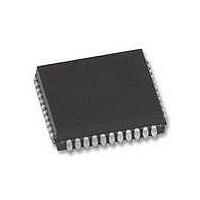
XR88C681J-F Exar Corporation, XR88C681J-F Datasheet - Page 52

XR88C681J-F
Manufacturer Part Number
XR88C681J-F
Description
IC UART CMOS DUAL 44PLCC
Manufacturer
Exar Corporation
Type
CMOS Dual Channel UARTr
Datasheet
1.XR88C681CP40-F.pdf
(101 pages)
Specifications of XR88C681J-F
Number Of Channels
2, DUART
Package / Case
44-LCC (J-Lead)
Features
*
Fifo's
1 Byte, 3 Byte
Voltage - Supply
5V
With Parallel Port
Yes
With Cmos
Yes
Mounting Type
Surface Mount
Data Rate
1 Mbps
Supply Voltage (max)
5.25 V
Supply Voltage (min)
4.75 V
Supply Current
15 mA
Maximum Operating Temperature
+ 85 C
Minimum Operating Temperature
- 40 C
Mounting Style
SMD/SMT
Operating Supply Voltage
5 V
Propagation Delay Time Ns
400 ns
No. Of Channels
2
Supply Voltage Range
4.75V To 5.25V
Operating Temperature Range
-40°C To +85°C
Digital Ic Case Style
PLCC
No. Of Pins
44
Filter Terminals
SMD
Rohs Compliant
Yes
Lead Free Status / RoHS Status
Lead free / RoHS Compliant
Lead Free Status / RoHS Status
Lead free / RoHS Compliant, Lead free / RoHS Compliant
Other names
1016-1329
Available stocks
Company
Part Number
Manufacturer
Quantity
Price
Company:
Part Number:
XR88C681J-F
Manufacturer:
Exar Corporation
Quantity:
10 000
Note: The user also has an option to drive the Oscillator Circuit with a TTL input signal, in lieu of using a crystal oscillator. If this
If the user desires to run numerous DUARTs from a single crystal oscillator, Figure 26 presents an approach and the
necessary circuitry to accomplish this objective.
Note: The user is urged not to use the 74LS14 Schmitt Trigger Inverter in lieu of the 74HC14 device. The input of the 74LS14 tends to
Figure 26. A Recommended Schematic to Drive Multiple DUARTs From the Same Crystal Oscillator.
Rev. 2.11
approach is used, the TTL must be driven into the X1/CLK pin, and the X2 pin must be left floating.
load down the oscillating signal from the DUART, to the point that the Schmitt Trigger inverter can no longer change state or
respond to the oscillator signal.
Figure 25. A Recommended Schematic for the XTAL Oscillator Circuitry
C1
C2
3.6864MHz
X1
Parallel Resonant Crystal
C1: 10pF + (Stray < 5pF)
C2: 10pF + (Stray < 5pF)
R1: 100ohm
R2: 100ohm
XR88C681
3.684MHz
Y1
52
X2
R1
R2
X1
X2
XR88C681
74HC14
To X1 inputs of
other DUARTs


