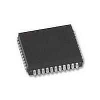
XR88C681J-F Exar Corporation, XR88C681J-F Datasheet - Page 19

XR88C681J-F
Manufacturer Part Number
XR88C681J-F
Description
IC UART CMOS DUAL 44PLCC
Manufacturer
Exar Corporation
Type
CMOS Dual Channel UARTr
Datasheet
1.XR88C681CP40-F.pdf
(101 pages)
Specifications of XR88C681J-F
Number Of Channels
2, DUART
Package / Case
44-LCC (J-Lead)
Features
*
Fifo's
1 Byte, 3 Byte
Voltage - Supply
5V
With Parallel Port
Yes
With Cmos
Yes
Mounting Type
Surface Mount
Data Rate
1 Mbps
Supply Voltage (max)
5.25 V
Supply Voltage (min)
4.75 V
Supply Current
15 mA
Maximum Operating Temperature
+ 85 C
Minimum Operating Temperature
- 40 C
Mounting Style
SMD/SMT
Operating Supply Voltage
5 V
Propagation Delay Time Ns
400 ns
No. Of Channels
2
Supply Voltage Range
4.75V To 5.25V
Operating Temperature Range
-40°C To +85°C
Digital Ic Case Style
PLCC
No. Of Pins
44
Filter Terminals
SMD
Rohs Compliant
Yes
Lead Free Status / RoHS Status
Lead free / RoHS Compliant
Lead Free Status / RoHS Status
Lead free / RoHS Compliant, Lead free / RoHS Compliant
Other names
1016-1329
Available stocks
Company
Part Number
Manufacturer
Quantity
Price
Company:
Part Number:
XR88C681J-F
Manufacturer:
Exar Corporation
Quantity:
10 000
C. INTERRUPT CONTROL BLOCK
The Interrupt Control Block allows the user to apply the
DUART in an “Interrupt Driven” environment.
DUART includes an interrupt request output signal
(
the occurrence of any of the following events:
D Transmit Hold Register A or B Ready
D Receive Hold Register A or B Ready
The role and purpose of each of these registers are
defined here.
C.1 Interrupt Status Registers (ISR)
The contents of the ISR indicates the status of all potential
interrupt conditions. If any bits within these registers are
toggled “high”, then the corresponding condition has or is
The definition of the meaning behind each of these bits is
presented here.
ISR[7]: Input Port Change of State
If this bit is at a logic “1”, then a change of state was
detected at Input Port pins IP0 - IP3. The user would
service this interrupt by reading the IPCR (if ISR[7] = 1).
ISR[7] is cleared when the CPU has read the Input Port
Configuration Register (IPCR). By reading the IPCR, the
user will determine:
-
INTR), which may be programmed to be asserted upon
Input Port
Change
1 = Yes
0 = No
Rev. 2.11
Bit 7
Delta Break
1 = Yes
0 = No
Bit 6
B
Table 4. Listing and Brief Description of Interrupt System Registers
Register
MISR
IMR
ISR
IVR
FFULLB
RXRDY/
1 = Yes
0 = No
Bit 5
Masked Interrupt Status Register
Interrupt Status Register
Interrupt Vector Register
Interrupt Mask Register
Table 5. ISR Bit Format
TXRDYB
1 = Yes
0 = No
Bit 4
Description
The
19
D Receive FIFO A or B Full
D Start or End of Received Break in Channels A or B
D End of Counter/Timer Count Reached
D Change of State on input pins, IP0, IP1, IP2, IP3
The Interrupt Control Block consists of an Interrupt Status
Registers (ISR), an Interrupt Mask Registers (IMR), a
Masked Interrupt Status Registers (MISR) and an
Interrupt Vector Register (IVR).
registers, their address location (within the DUART).
occurring. In general, the contents of the ISR will indicate
to the processor, the source or the reason for the Interrupt
Request from the DUART.
service routine for the DUART should begin by reading
either this register or the MISR (Masked Interrupt Status
Register). The bit-format of the ISR is presented in
Table 5:
D The individual Input Port pin that changed state
D The final state of the monitored input ports, following
For a detailed description of the IPCR, see Section F.
Please note that in order to enable this Interrupt
Condition, the user must do two things:
1. Write the appropriate data to the lower nibble of the
Counter
1 = Yes
Ready
0 = No
Bit 3
the Change of State.
Auxiliary Control Register, ACR[3:0]. In this step, the
user is specifying which Input Pins should trigger an
“Input Port Change” Interrupt request.
Delta Break
(in DUART Address Space)
1 = Yes
0 = No
Bit 2
A
Address Location
05
05
02
16
16
16
(Read Only)
(Read Only)
(Write Only)
0C
XR88C681
16
FFULLA
RXRDY/
Therefore, any interrupt
1 = Yes
0 = No
Bit 1
Table 4 lists these
TXRDYA
1 = Yes
0 = No
Bit 0


