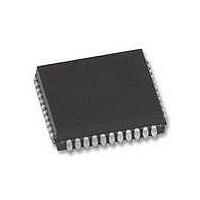
XR88C681J-F Exar Corporation, XR88C681J-F Datasheet - Page 40

XR88C681J-F
Manufacturer Part Number
XR88C681J-F
Description
IC UART CMOS DUAL 44PLCC
Manufacturer
Exar Corporation
Type
CMOS Dual Channel UARTr
Datasheet
1.XR88C681CP40-F.pdf
(101 pages)
Specifications of XR88C681J-F
Number Of Channels
2, DUART
Package / Case
44-LCC (J-Lead)
Features
*
Fifo's
1 Byte, 3 Byte
Voltage - Supply
5V
With Parallel Port
Yes
With Cmos
Yes
Mounting Type
Surface Mount
Data Rate
1 Mbps
Supply Voltage (max)
5.25 V
Supply Voltage (min)
4.75 V
Supply Current
15 mA
Maximum Operating Temperature
+ 85 C
Minimum Operating Temperature
- 40 C
Mounting Style
SMD/SMT
Operating Supply Voltage
5 V
Propagation Delay Time Ns
400 ns
No. Of Channels
2
Supply Voltage Range
4.75V To 5.25V
Operating Temperature Range
-40°C To +85°C
Digital Ic Case Style
PLCC
No. Of Pins
44
Filter Terminals
SMD
Rohs Compliant
Yes
Lead Free Status / RoHS Status
Lead free / RoHS Compliant
Lead Free Status / RoHS Status
Lead free / RoHS Compliant, Lead free / RoHS Compliant
Other names
1016-1329
Available stocks
Company
Part Number
Manufacturer
Quantity
Price
Company:
Part Number:
XR88C681J-F
Manufacturer:
Exar Corporation
Quantity:
10 000
In addition to the
DUART also uses the IEI and IEO pins; which are defined
as follows:
IEI - Interrupt Enable Input
This active-high input is only available if the DUART is
configured to operate in the Z-Mode. If this input is at a
logic “high” then all unmasked interrupt requests, from
this DUART, are enabled.
Note:
IEO - Interrupt Enable Output
This active-high output is only available if the DUART is
configured to operate in the Z-Mode. This output is often
times connected to the IEI input of another (lower priority)
device.
conditions are true.
D The device’s IEI input is at a logic “high”
D The device is not requesting an interrupt from the
Those interrupts which have been masked out by the IMR are
still disabled. However, if this input is at a logic “low”, then all
interrupts (whether masked or unmasked) are disabled.
Hence, IEI can act to globally disable all DUART interrupt
requests.
CPU
Rev. 2.11
CPU
This output is “high” if all of the following
-IACK
-INT
-
INTR and
Figure 15. A Diagram of Numerous DUARTs Configured in an Interrupt
V
CC
V
-
IACK pins, the Z-Mode
CC
IEI
HIGHEST
-INTR
-IACK
Daisy Chain (for Z-Mode Operation)
IEO
IEI
-INTR
-IACK
40
D An interrupt, requested by the device, has just been
If any of these conditions are false, then the IEO pin will be
at a logic “low”.
Note:
System Level Application of the IEI and IEO pins
Figure 15 depicts a series of DUARTs connected in a
daisy-chain fashion. In this figure, the left-most DUART
has the highest interrupt priority. This is because this
DUART’s IEI input is hardwired to Vcc. Therefore, the
unmasked interrupt requests, from this DUART are
always enabled. The DUART device, located just to the
right of the “highest interrupt priority” device is of a lower
interrupt priority. This is because the IEI input of this lower
priority device is connected to the IEO output of the
highest priority DUART. Whenever the “highest priority”
device requests an interrupt, its IEO output will toggle
“low”. This will in turn, disable the “lower priority” device
Once the IEO pin has toggled “low”, and the CPU has ac-
knowledged the interrupt request and has completed the inter-
rupt service routine, the IEO pin will remain “low” until the user
invokes the “RESET IUS” command (see Table 3). Therefore,
if the DUART is going to operate in the Z-Mode, the user must
include the “RESET IUS” Command at the very end of the
DUART interrupt service routine.
IEO
serviced
PRIORITY
IEI
-INTR
-IACK
IEO
IEI
LOWEST
-INTR
-IACK
IEO


