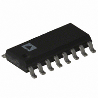
AD605ARZ Analog Devices Inc, AD605ARZ Datasheet - Page 2

AD605ARZ
Manufacturer Part Number
AD605ARZ
Description
IC AMP VGA DUAL LN 40MA 16SOIC
Manufacturer
Analog Devices Inc
Series
X-AMP®r
Type
Variable Gain Amplifierr
Datasheet
1.AD605-EVALZ.pdf
(24 pages)
Specifications of AD605ARZ
Amplifier Type
Variable Gain
Number Of Circuits
2
Slew Rate
170 V/µs
-3db Bandwidth
40MHz
Current - Input Bias
400nA
Current - Supply
18mA
Current - Output / Channel
40mA
Voltage - Supply, Single/dual (±)
4.5 V ~ 5.5 V
Operating Temperature
-40°C ~ 85°C
Mounting Type
Surface Mount
Package / Case
16-SOIC (3.9mm Width)
No. Of Amplifiers
1
Bandwidth
40MHz
Gain Accuracy
1.2dB
No. Of Channels
2
Supply Voltage Range
4.5V To 5.5V
Amplifier Case Style
SOIC
No. Of Pins
16
Number Of Channels
2
Number Of Elements
2
Power Supply Requirement
Single
Common Mode Rejection Ratio
20dB
Voltage Gain Db
34dB
Input Resistance
0.000175@5VMohm
Input Bias Current
0.4@5VnA
Single Supply Voltage (typ)
5V
Dual Supply Voltage (typ)
Not RequiredV
Power Dissipation
90W
Rail/rail I/o Type
No
Single Supply Voltage (min)
4.5V
Single Supply Voltage (max)
5.5V
Dual Supply Voltage (min)
Not RequiredV
Dual Supply Voltage (max)
Not RequiredV
Operating Temp Range
-40C to 85C
Operating Temperature Classification
Industrial
Mounting
Surface Mount
Pin Count
16
Package Type
SOIC N
Lead Free Status / RoHS Status
Lead free / RoHS Compliant
For Use With
AD605-EVALZ - BOARD EVALUATION FOR AD605
Output Type
-
Gain Bandwidth Product
-
Voltage - Input Offset
-
Lead Free Status / Rohs Status
Compliant
Available stocks
Company
Part Number
Manufacturer
Quantity
Price
Part Number:
AD605ARZ
Manufacturer:
ADI/亚德诺
Quantity:
20 000
Company:
Part Number:
AD605ARZ-RL
Manufacturer:
PANASONIC
Quantity:
20 000
AD605
TABLE OF CONTENTS
Features .............................................................................................. 1
Applications ....................................................................................... 1
Functional Block Diagram .............................................................. 1
General Description ......................................................................... 1
Revision History ............................................................................... 2
Specifications ..................................................................................... 3
Absolute Maximum Ratings ............................................................ 5
Pin Configuration and Function Descriptions ............................. 6
Typical Performance Characteristics (per Channel) ................... 7
Theory of Operation ...................................................................... 13
REVISION HISTORY
6/08—Rev. E to Rev. F
Added Evaluation Board Section ................................................. 18
Added Figure 42 and Table 4......................................................... 18
Added Figure 43 and Figure 44..................................................... 19
Added Figure 45 to Figure 50 ........................................................ 20
5/07—Rev. D to Rev. E
Changes to Table 1 ............................................................................ 5
Changes to Fixed Gain Amplifier and Interpolator Circuits—
Applying an Active Feedback Amplifier Section ........................ 15
Updated Outline Dimensions ....................................................... 18
Changes to Ordering Guide .......................................................... 19
1/06—Rev. C to Rev. D
Updated Format .................................................................. Universal
Changes to Table 2 ............................................................................ 5
Changes to Differential Ladder (Attenuator) Section ............... 14
Updated the Outline Dimensions ................................................ 18
Changes to the Ordering Guide .................................................... 19
ESD Caution .................................................................................. 5
Differential Ladder (Attenuator) .............................................. 14
AC Coupling ............................................................................... 14
Rev. F | Page 2 of 24
Applications Information .............................................................. 16
Evaluation Board ............................................................................ 18
Outline Dimensions ....................................................................... 21
7/04—Rev. B to Rev. C
Edits to General Description ........................................................... 1
Edits to Specifications ....................................................................... 2
Edits to Ordering Guide ................................................................... 3
Change to TPC 22 ............................................................................. 6
Updated Outline Dimensions ....................................................... 12
Gain Control Interface ............................................................... 14
Fixed Gain Amplifier and Interpolator Circuits—Applying an
Active Feedback Amplifier ........................................................ 15
Connecting Two Amplifiers to Double the Gain Range ....... 16
Input Connections ..................................................................... 18
Adjusting Gain, Common-Mode, and Reference Levels ...... 18
Output Connections .................................................................. 18
Ordering Guide .......................................................................... 22


