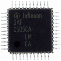
SAF-C515C-8EM CA Infineon Technologies, SAF-C515C-8EM CA Datasheet - Page 40

SAF-C515C-8EM CA
Manufacturer Part Number
SAF-C515C-8EM CA
Description
IC MCU 8BIT OTP MQFP-80-1
Manufacturer
Infineon Technologies
Series
C5xx/C8xxr
Datasheet
1.SAF-C515C-8EM_CA.pdf
(96 pages)
Specifications of SAF-C515C-8EM CA
Core Processor
C500
Core Size
8-Bit
Speed
10MHz
Connectivity
CAN, EBI/EMI, SPI, UART/USART
Peripherals
POR, PWM, WDT
Number Of I /o
49
Program Memory Size
64KB (64K x 8)
Program Memory Type
OTP
Ram Size
2.5K x 8
Voltage - Supply (vcc/vdd)
4.25 V ~ 5.5 V
Data Converters
A/D 8x10b
Oscillator Type
External
Operating Temperature
-40°C ~ 85°C
Package / Case
80-SQFP
Data Bus Width
8 bit
Data Ram Size
2.25 KB
Interface Type
USART, SSC
Maximum Clock Frequency
10 MHz
Number Of Programmable I/os
49
Number Of Timers
3
Operating Supply Voltage
5 V
Maximum Operating Temperature
+ 85 C
Mounting Style
SMD/SMT
Minimum Operating Temperature
- 40 C
On-chip Adc
10 bit, 8 Channel
Packages
PG-MQFP-80
Max Clock Frequency
10.0 MHz
Sram (incl. Cache)
2.25 KByte
Can Nodes
1
A / D Input Lines (incl. Fadc)
8
Program Memory
64.0 KByte
Lead Free Status / RoHS Status
Lead free / RoHS Compliant
Eeprom Size
-
Lead Free Status / Rohs Status
Details
Other names
F515C8EMCANP
F515C8EMCAXT
SAF-C515C-8EMCA
SAF-C515C-8EMCA
SAF-C515C-8EMCAIN
SAFC515C8EMCAX
SP000068749
SP000106399
F515C8EMCAXT
SAF-C515C-8EMCA
SAF-C515C-8EMCA
SAF-C515C-8EMCAIN
SAFC515C8EMCAX
SP000068749
SP000106399
C515C
Timer 2 Operating Modes
The timer 2, which is a 16-bit-wide register, can operate as timer, event counter, or gated
timer. A roll-over of the count value in TL2/TH2 from all 1’s to all 0’s sets the timer
overflow flag TF2 in SFR IRCON, which can generate an interrupt. The bits in register
T2CON are used to control the timer 2 operation.
Timer Mode: In timer function, the count rate is derived from the oscillator frequency. A
prescaler offers the possibility of selecting a count rate of 1/6 or 1/12 of the oscillator
frequency.
Gated Timer Mode: In gated timer function, the external input pin T2 (P1.7) functions as
a gate to the input of timer 2. If T2 is high, the internal clock input is gated to the timer.
T2 = 0 stops the counting procedure. This facilitates pulse width measurements. The
external gate signal is sampled once every machine cycle.
Event Counter Mode: In the event counter function. the timer 2 is incremented in
response to a 1-to-0 transition at its corresponding external input pin T2 (P1.7). In this
function, the external input is sampled every machine cycle. Since it takes two machine
cycles (12 oscillator periods) to recognize a 1-to-0 transition, the maximum count rate is
1/12 of the oscillator frequency. There are no restrictions on the duty cycle of the external
input signal, but to ensure that a given level is sampled at least once before it changes,
it must be held for at least one full machine cycle.
Reload of Timer 2: Two reload modes are selectable:
In mode 0, when timer 2 rolls over from all 1’s to all 0’s, it not only sets TF2 but also
causes the timer 2 registers to be loaded with the 16-bit value in the CRC register, which
is preset by software.
In mode 1, a 16-bit reload from the CRC register is caused by a negative transition at the
corresponding input pin P1.5/T2EX. This transition will also set flag EXF2 if bit EXEN2
in SFR IEN1 has been set.
Data Sheet
36
2003-02


