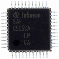
SAF-C515C-8EM CA Infineon Technologies, SAF-C515C-8EM CA Datasheet - Page 12

SAF-C515C-8EM CA
Manufacturer Part Number
SAF-C515C-8EM CA
Description
IC MCU 8BIT OTP MQFP-80-1
Manufacturer
Infineon Technologies
Series
C5xx/C8xxr
Datasheet
1.SAF-C515C-8EM_CA.pdf
(96 pages)
Specifications of SAF-C515C-8EM CA
Core Processor
C500
Core Size
8-Bit
Speed
10MHz
Connectivity
CAN, EBI/EMI, SPI, UART/USART
Peripherals
POR, PWM, WDT
Number Of I /o
49
Program Memory Size
64KB (64K x 8)
Program Memory Type
OTP
Ram Size
2.5K x 8
Voltage - Supply (vcc/vdd)
4.25 V ~ 5.5 V
Data Converters
A/D 8x10b
Oscillator Type
External
Operating Temperature
-40°C ~ 85°C
Package / Case
80-SQFP
Data Bus Width
8 bit
Data Ram Size
2.25 KB
Interface Type
USART, SSC
Maximum Clock Frequency
10 MHz
Number Of Programmable I/os
49
Number Of Timers
3
Operating Supply Voltage
5 V
Maximum Operating Temperature
+ 85 C
Mounting Style
SMD/SMT
Minimum Operating Temperature
- 40 C
On-chip Adc
10 bit, 8 Channel
Packages
PG-MQFP-80
Max Clock Frequency
10.0 MHz
Sram (incl. Cache)
2.25 KByte
Can Nodes
1
A / D Input Lines (incl. Fadc)
8
Program Memory
64.0 KByte
Lead Free Status / RoHS Status
Lead free / RoHS Compliant
Eeprom Size
-
Lead Free Status / Rohs Status
Details
Other names
F515C8EMCANP
F515C8EMCAXT
SAF-C515C-8EMCA
SAF-C515C-8EMCA
SAF-C515C-8EMCAIN
SAFC515C8EMCAX
SP000068749
SP000106399
F515C8EMCAXT
SAF-C515C-8EMCA
SAF-C515C-8EMCA
SAF-C515C-8EMCAIN
SAFC515C8EMCAX
SP000068749
SP000106399
Table 2
Symbol
P1.0 - P1.7 31-24
XTAL2
Data Sheet
Pin Number
P-MQFP-80-1
31
30
29
28
27
26
25
24
36
Pin Definitions and Functions (cont’d)
I/O
I/O
I
1)
Function
Port 1
is an 8-bit quasi-bidirectional I/O port with internal
pullup resistors. Port 1 pins that have 1's written to
them are pulled high by the internal pullup resistors,
and in that state can be used as inputs. As inputs,
port 1 pins being externally pulled low will source
current (
the internal pullup resistors. The port is used for the
low-order address byte during program verification.
Port 1 also contains the interrupt, timer, clock,
capture and compare pins that are used by various
options. The output latch corresponding to a
secondary function must be programmed to a one
(1) for that function to operate (except when used for
the compare functions). The secondary functions
are assigned to the port 1 pins as follows:
P1.0 INT3 CC0 Interrupt 3 input / compare 0
P1.1 INT4 CC1 Interrupt 4 input / compare 1
P1.2 INT5 CC2 Interrupt 5 input / compare 2
P1.3 INT6 CC3 Interrupt 6 input / compare 3
P1.4 INT2
P1.5 T2EX
P1.6 CLKOUT
P1.7 T2
XTAL2
Input to the inverting oscillator amplifier and input to
the internal clock generator circuits.
To drive the device from an external clock source,
XTAL2 should be driven, while XTAL1 is left
unconnected. Minimum and maximum high and low
times as well as rise/fall times specified in the AC
characteristics must be observed.
8
I
IL
, in the DC characteristics) because of
output / capture 0 input
output / capture 1 input
output / capture 2 input
output / capture 3 input
Interrupt 2 input
Timer 2 external reload / trigger
input
System clock output
Counter 2 input
C515C
2003-02


