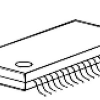
SAA-XC866L-1FRA AB Infineon Technologies, SAA-XC866L-1FRA AB Datasheet - Page 63

SAA-XC866L-1FRA AB
Manufacturer Part Number
SAA-XC866L-1FRA AB
Description
IC MCU 8BIT 4KB FLASH 38TSSOP
Manufacturer
Infineon Technologies
Series
XC8xxr
Datasheet
1.SAA-XC866-1FRA_AB.pdf
(114 pages)
Specifications of SAA-XC866L-1FRA AB
Core Processor
XC800
Core Size
8-Bit
Speed
86MHz
Connectivity
LIN, SSI, UART/USART
Peripherals
Brown-out Detect/Reset, POR, PWM, WDT
Number Of I /o
27
Program Memory Size
4KB (4K x 8)
Program Memory Type
FLASH
Ram Size
768 x 8
Voltage - Supply (vcc/vdd)
2.3 V ~ 5.5 V
Data Converters
A/D 8x10b
Oscillator Type
Internal
Operating Temperature
-40°C ~ 140°C
Package / Case
38-TSSOP
Data Bus Width
8 bit
Data Ram Size
750 B
Interface Type
UART, SSC
Maximum Clock Frequency
26.67 MHz
Number Of Programmable I/os
27
Number Of Timers
3
Operating Supply Voltage
3.3 V, 5 V
Maximum Operating Temperature
+ 85 C
Mounting Style
SMD/SMT
Minimum Operating Temperature
- 40 C
Lead Free Status / RoHS Status
Lead free / RoHS Compliant
Eeprom Size
-
Lead Free Status / Rohs Status
Details
The clock system provides three ways to generate the system clock:
PLL Base Mode
The system clock is derived from the VCO base (free running) frequency clock divided
by the K factor.
Prescaler Mode (VCO Bypass Operation)
In VCO bypass operation, the system clock is derived from the oscillator clock, divided
by the P and K factors.
PLL Mode
The system clock is derived from the oscillator clock, multiplied by the N factor, and
divided by the P and K factors. Both VCO bypass and PLL bypass must be inactive for
this PLL mode. The PLL mode is used during normal system operation.
Table 20
selection.
Table 20
OSCDISC
0
0
1
1
Note: When oscillator clock is disconnected from PLL, the clock mode is PLL Base mode
System Frequency Selection
For the SAA-XC866, the values of P and K are fixed to “1” and “2”, respectively. In order
to obtain the required system frequency, f
for different oscillator inputs.
obtained for the different oscillator sources.
Data Sheet
regardless of the setting of VCOBYP bit.
shows the settings of bits OSCDISC and VCOBYP for different clock mode
Clock Mode Selection
VCOBYP
0
1
0
1
Table 21
f
f
SYS
SYS
f
SYS
=
=
=
provides examples on how f
f
f
VCObase
OSC
f
Clock Working Modes
PLL Mode
Prescaler Mode
PLL Base Mode
PLL Base Mode
sys
OSC
60
, the value of N can be selected by bit NDIV
×
×
-------------
P
-------------
P K
N
×
×
×
1
K
--- -
K
1
Functional Description
sys
= 80 MHz can be
SAA-XC866
V1.5, 2010-09


