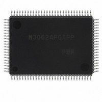
M30624FGAFP#U3 Renesas Electronics America, M30624FGAFP#U3 Datasheet - Page 13

M30624FGAFP#U3
Manufacturer Part Number
M30624FGAFP#U3
Description
IC M16C MCU FLASH 100QFP
Manufacturer
Renesas Electronics America
Series
M16C™ M16C/60r
Datasheets
1.M30622SAFPU5.pdf
(277 pages)
2.M30622SAFPU5.pdf
(617 pages)
3.M30622SAFPU5.pdf
(308 pages)
Specifications of M30624FGAFP#U3
Core Processor
M16C/60
Core Size
16-Bit
Speed
16MHz
Connectivity
SIO, UART/USART
Peripherals
DMA, PWM, WDT
Number Of I /o
85
Program Memory Size
256KB (256K x 8)
Program Memory Type
FLASH
Ram Size
20K x 8
Voltage - Supply (vcc/vdd)
4.2 V ~ 5.5 V
Data Converters
A/D 10x10b, D/A 2x8b
Oscillator Type
Internal
Operating Temperature
-40°C ~ 85°C
Package / Case
100-QFP
For Use With
867-1000 - KIT QUICK START RENESAS 62PM3062PT3-CPE-3 - EMULATOR COMPACT M16C/62P/30P
Lead Free Status / RoHS Status
Lead free / RoHS Compliant
Eeprom Size
-
Available stocks
Company
Part Number
Manufacturer
Quantity
Price
Part Number:
M30624FGAFP#U3M30624FGAFP#D3
Manufacturer:
Renesas Electronics America
Quantity:
10 000
Part Number:
M30624FGAFP#U3M30624FGAFP#D5
Manufacturer:
Renesas Electronics America
Quantity:
10 000
- Current page: 13 of 617
- Download datasheet (9Mb)
Chapter 3 Examples of Peripheral functions Applications ________
Chapter 4 External Buses ___________________________________
2.12 Address Match Interrupt Usage ............................................................................................ 2-158
2.13 Key-Input Interrupt Usage ..................................................................................................... 2-162
2.14 Multiple interrupts usage ....................................................................................................... 2-166
2.15 Power Control Usage ............................................................................................................ 2-173
2.16 Programmable I/O Ports Usage ............................................................................................ 2-181
3.1 Long-Period Timers ................................................................................................................ 2-192
3.2 Variable-Period Variable-Duty PWM Output ........................................................................... 2-196
3.3 Delayed One-Shot Output ...................................................................................................... 2-200
3.4 Buzzer Output ......................................................................................................................... 2-204
3.5 Solution for External Interrupt Pins Shortage ......................................................................... 2-206
3.6 Memory to Memory DMA Transfer .......................................................................................... 2-208
3.7 Controlling Power Using Stop Mode ....................................................................................... 2-212
3.8 Controling Power Using Wait Mode ........................................................................................ 2-216
4.1 Overview of External Buses .................................................................................................... 2-222
4.2 Data Access ............................................................................................................................ 2-223
2.11.1 Overview of the watchdog timer usage .......................................................................... 2-154
2.11.2 Operation of Watchdog Timer ........................................................................................ 2-156
2.12.1 Overview of the address match interrupt usage ............................................................ 2-158
2.12.2 Operation of Address Match Interrupt ............................................................................ 2-160
2.13.1 Overview of the key-input interrupt usage ..................................................................... 2-162
2.13.2 Operation of Key-Input Interrupt .................................................................................... 2-164
2.14.1 Overview of the Multiple interrupts usage ...................................................................... 2-166
2.14.2 Multiple Interrupts operation .......................................................................................... 2-171
2.15.1 Overview of the power control usage ............................................................................ 2-173
2.15.2 Stop Mode Set-Up ......................................................................................................... 2-178
2.15.3 Wait Mode Set-Up ......................................................................................................... 2-179
2.15.4 Precautions in Power Control ........................................................................................ 2-180
2.16.1 Overview of the programmable I/O ports usage ............................................................ 2-181
4.2.1 Data Bus Width ................................................................................................................ 2-223
4.2.2 Chip Selects and Address Bus ........................................................................................ 2-224
4.2.3 Bus Types ....................................................................................................................... 2-225
4.2.4 R/W Modes ..................................................................................................................... 2-225
Related parts for M30624FGAFP#U3
Image
Part Number
Description
Manufacturer
Datasheet
Request
R

Part Number:
Description:
KIT STARTER FOR M16C/29
Manufacturer:
Renesas Electronics America
Datasheet:

Part Number:
Description:
KIT STARTER FOR R8C/2D
Manufacturer:
Renesas Electronics America
Datasheet:

Part Number:
Description:
R0K33062P STARTER KIT
Manufacturer:
Renesas Electronics America
Datasheet:

Part Number:
Description:
KIT STARTER FOR R8C/23 E8A
Manufacturer:
Renesas Electronics America
Datasheet:

Part Number:
Description:
KIT STARTER FOR R8C/25
Manufacturer:
Renesas Electronics America
Datasheet:

Part Number:
Description:
KIT STARTER H8S2456 SHARPE DSPLY
Manufacturer:
Renesas Electronics America
Datasheet:

Part Number:
Description:
KIT STARTER FOR R8C38C
Manufacturer:
Renesas Electronics America
Datasheet:

Part Number:
Description:
KIT STARTER FOR R8C35C
Manufacturer:
Renesas Electronics America
Datasheet:

Part Number:
Description:
KIT STARTER FOR R8CL3AC+LCD APPS
Manufacturer:
Renesas Electronics America
Datasheet:

Part Number:
Description:
KIT STARTER FOR RX610
Manufacturer:
Renesas Electronics America
Datasheet:

Part Number:
Description:
KIT STARTER FOR R32C/118
Manufacturer:
Renesas Electronics America
Datasheet:

Part Number:
Description:
KIT DEV RSK-R8C/26-29
Manufacturer:
Renesas Electronics America
Datasheet:

Part Number:
Description:
KIT STARTER FOR SH7124
Manufacturer:
Renesas Electronics America
Datasheet:

Part Number:
Description:
KIT STARTER FOR H8SX/1622
Manufacturer:
Renesas Electronics America
Datasheet:

Part Number:
Description:
KIT DEV FOR SH7203
Manufacturer:
Renesas Electronics America
Datasheet:


