DF2377RVFQ33W Renesas Electronics America, DF2377RVFQ33W Datasheet - Page 189
DF2377RVFQ33W
Manufacturer Part Number
DF2377RVFQ33W
Description
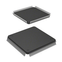
IC H8S MCU FLASH 3V 384K 144LQFP
Manufacturer
Renesas Electronics America
Series
H8® H8S/2300r
Datasheet
1.YR0K42378FC000BA.pdf
(1208 pages)
Specifications of DF2377RVFQ33W
Core Processor
H8S/2000
Core Size
16-Bit
Speed
33MHz
Connectivity
I²C, IrDA, SCI, SmartCard
Peripherals
DMA, POR, PWM, WDT
Number Of I /o
97
Program Memory Size
384KB (384K x 8)
Program Memory Type
FLASH
Ram Size
24K x 8
Voltage - Supply (vcc/vdd)
3 V ~ 3.6 V
Data Converters
A/D 16x10b; D/A 6x8b
Oscillator Type
Internal
Operating Temperature
-40°C ~ 85°C
Package / Case
144-LQFP
Lead Free Status / RoHS Status
Contains lead / RoHS non-compliant
Eeprom Size
-
Available stocks
Company
Part Number
Manufacturer
Quantity
Price
Company:

Part Number:
DF2377RVFQ33W
Manufacturer:
Renesas Electronics America
Quantity:
10 000
Company:
Part Number:
DF2377RVFQ33WV
Manufacturer:
Renesas Electronics America
Quantity:
10 000


5.4.2
The sources for internal interrupts from on-chip peripheral modules have the following features:
• For each on-chip peripheral module there are flags that indicate the interrupt request status,
• The interrupt priority level can be set by means of IPR.
• The DMAC and DTC can be activated by a TPU, SCI, or other interrupt request.
• When the DMAC or DTC is activated by an interrupt request, it is not affected by the interrupt
5.5
Table 5.2 shows interrupt exception handling sources, vector addresses, and interrupt priorities.
For default priorities, the lower the vector number, the higher the priority. When interrupt control
mode 2 is set, priorities among modules can be set by means of the IPR. Modules set at the same
priority will conform to their default priorities. Priorities within a module are fixed.
IRQn
input
and enable bits that select enabling or disabling of these interrupts. They can be controlled
independently. When the enable bit is set to 1, an interrupt request is issued to the interrupt
controller.
control mode or CPU interrupt mask bit.
Note: n = 15 to 0
Internal Interrupts
Interrupt Exception Handling Vector Table
Figure 5.2 Block Diagram of Interrupts IRQ15 to IRQ0
IRQnSCA, IRQnSCB
level detection
Edge/
circuit
Clear signal
R
S
IRQnF
Rev.7.00 Mar. 18, 2009 page 121 of 1136
Q
IRQnE
Section 5 Interrupt Controller
REJ09B0109-0700
IRQn interrupt
request
Related parts for DF2377RVFQ33W
Image
Part Number
Description
Manufacturer
Datasheet
Request
R

Part Number:
Description:
KIT STARTER FOR M16C/29
Manufacturer:
Renesas Electronics America
Datasheet:

Part Number:
Description:
KIT STARTER FOR R8C/2D
Manufacturer:
Renesas Electronics America
Datasheet:

Part Number:
Description:
R0K33062P STARTER KIT
Manufacturer:
Renesas Electronics America
Datasheet:

Part Number:
Description:
KIT STARTER FOR R8C/23 E8A
Manufacturer:
Renesas Electronics America
Datasheet:

Part Number:
Description:
KIT STARTER FOR R8C/25
Manufacturer:
Renesas Electronics America
Datasheet:

Part Number:
Description:
KIT STARTER H8S2456 SHARPE DSPLY
Manufacturer:
Renesas Electronics America
Datasheet:

Part Number:
Description:
KIT STARTER FOR R8C38C
Manufacturer:
Renesas Electronics America
Datasheet:

Part Number:
Description:
KIT STARTER FOR R8C35C
Manufacturer:
Renesas Electronics America
Datasheet:

Part Number:
Description:
KIT STARTER FOR R8CL3AC+LCD APPS
Manufacturer:
Renesas Electronics America
Datasheet:
Part Number:
Description:
KIT STARTER FOR RX610
Manufacturer:
Renesas Electronics America
Datasheet:

Part Number:
Description:
KIT STARTER FOR R32C/118
Manufacturer:
Renesas Electronics America
Datasheet:

Part Number:
Description:
KIT DEV RSK-R8C/26-29
Manufacturer:
Renesas Electronics America
Datasheet:

Part Number:
Description:
KIT STARTER FOR SH7124
Manufacturer:
Renesas Electronics America
Datasheet:

Part Number:
Description:
KIT STARTER FOR H8SX/1622
Manufacturer:
Renesas Electronics America
Datasheet:

Part Number:
Description:
KIT DEV FOR SH7203
Manufacturer:
Renesas Electronics America
Datasheet: