DF2377RVFQ33W Renesas Electronics America, DF2377RVFQ33W Datasheet - Page 1046
DF2377RVFQ33W
Manufacturer Part Number
DF2377RVFQ33W
Description
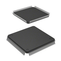
IC H8S MCU FLASH 3V 384K 144LQFP
Manufacturer
Renesas Electronics America
Series
H8® H8S/2300r
Datasheet
1.YR0K42378FC000BA.pdf
(1208 pages)
Specifications of DF2377RVFQ33W
Core Processor
H8S/2000
Core Size
16-Bit
Speed
33MHz
Connectivity
I²C, IrDA, SCI, SmartCard
Peripherals
DMA, POR, PWM, WDT
Number Of I /o
97
Program Memory Size
384KB (384K x 8)
Program Memory Type
FLASH
Ram Size
24K x 8
Voltage - Supply (vcc/vdd)
3 V ~ 3.6 V
Data Converters
A/D 16x10b; D/A 6x8b
Oscillator Type
Internal
Operating Temperature
-40°C ~ 85°C
Package / Case
144-LQFP
Lead Free Status / RoHS Status
Contains lead / RoHS non-compliant
Eeprom Size
-
Available stocks
Company
Part Number
Manufacturer
Quantity
Price
Company:

Part Number:
DF2377RVFQ33W
Manufacturer:
Renesas Electronics America
Quantity:
10 000
Company:
Part Number:
DF2377RVFQ33WV
Manufacturer:
Renesas Electronics America
Quantity:
10 000


Section 24 Power-Down Modes
24.2.5
Module stop mode can be set for individual on-chip peripheral modules.
When the corresponding MSTP bit in MSTPCR or EXMSTPCR is set to 1, module operation
stops at the end of the bus cycle and a transition is made to module stop mode. The CPU continues
operating independently.
When the corresponding MSTP bit is cleared to 0, module stop mode is cleared and the module
starts operating at the end of the bus cycle. In module stop mode, the internal states of modules
other than the SCI are retained.
After reset clearance, all modules other than the DMAC, and DTC are in module stop mode.
The module registers which are set in module stop mode cannot be read or written to.
24.2.6
When the ACSE bit in MSTPCRH is set to 1 and module stop mode is set for all the on-chip
peripheral functions controlled by MSTPCR or EXMSTPCR (MSTPCR = H'FFFF, EXMSTPCR
= H'FFFF), or for all the on-chip peripheral functions except the 8-bit timer (MSTPCR = H'FFFE,
EXMSTPCR = H'FFFF), executing a SLEEP instruction while the SSBY bit in SBYCR is cleared
to 0 will cause all the on-chip peripheral functions (except the 8-bit timer and watchdog timer), the
bus controller, and the I/O ports to stop operating, and a transition to be made to all-module-
clocks-stop mode, at the end of the bus cycle.
Operation or halting of the 8-bit timer can be selected by means of the MSTP0 bit.
Rev.7.00 Mar. 18, 2009 page 978 of 1136
REJ09B0109-0700
Module Stop Mode
All-Module-Clocks-Stop Mode
(1) Power supply
Figure 24.4 Hardware Standby Mode Timing when Power Is Supplied
STBY
RES
(2) Reset period
(3) Hardware standby mode
Related parts for DF2377RVFQ33W
Image
Part Number
Description
Manufacturer
Datasheet
Request
R

Part Number:
Description:
KIT STARTER FOR M16C/29
Manufacturer:
Renesas Electronics America
Datasheet:

Part Number:
Description:
KIT STARTER FOR R8C/2D
Manufacturer:
Renesas Electronics America
Datasheet:

Part Number:
Description:
R0K33062P STARTER KIT
Manufacturer:
Renesas Electronics America
Datasheet:

Part Number:
Description:
KIT STARTER FOR R8C/23 E8A
Manufacturer:
Renesas Electronics America
Datasheet:

Part Number:
Description:
KIT STARTER FOR R8C/25
Manufacturer:
Renesas Electronics America
Datasheet:

Part Number:
Description:
KIT STARTER H8S2456 SHARPE DSPLY
Manufacturer:
Renesas Electronics America
Datasheet:

Part Number:
Description:
KIT STARTER FOR R8C38C
Manufacturer:
Renesas Electronics America
Datasheet:

Part Number:
Description:
KIT STARTER FOR R8C35C
Manufacturer:
Renesas Electronics America
Datasheet:

Part Number:
Description:
KIT STARTER FOR R8CL3AC+LCD APPS
Manufacturer:
Renesas Electronics America
Datasheet:
Part Number:
Description:
KIT STARTER FOR RX610
Manufacturer:
Renesas Electronics America
Datasheet:

Part Number:
Description:
KIT STARTER FOR R32C/118
Manufacturer:
Renesas Electronics America
Datasheet:

Part Number:
Description:
KIT DEV RSK-R8C/26-29
Manufacturer:
Renesas Electronics America
Datasheet:

Part Number:
Description:
KIT STARTER FOR SH7124
Manufacturer:
Renesas Electronics America
Datasheet:

Part Number:
Description:
KIT STARTER FOR H8SX/1622
Manufacturer:
Renesas Electronics America
Datasheet:

Part Number:
Description:
KIT DEV FOR SH7203
Manufacturer:
Renesas Electronics America
Datasheet: