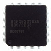
HD64F2633RTE28 Renesas Electronics America, HD64F2633RTE28 Datasheet - Page 328

HD64F2633RTE28
Manufacturer Part Number
HD64F2633RTE28
Description
IC H8S MCU FLASH 256K 120-TQFP
Manufacturer
Renesas Electronics America
Series
H8® H8S/2600r
Datasheet
1.D12312SVTE25V.pdf
(341 pages)
Specifications of HD64F2633RTE28
Core Processor
H8S/2600
Core Size
16-Bit
Speed
28MHz
Connectivity
I²C, IrDA, SCI, SmartCard
Peripherals
DMA, POR, PWM, WDT
Number Of I /o
73
Program Memory Size
256KB (256K x 8)
Program Memory Type
FLASH
Ram Size
16K x 8
Voltage - Supply (vcc/vdd)
3 V ~ 3.6 V
Data Converters
A/D 16x10b; D/A 4x8b
Oscillator Type
Internal
Operating Temperature
-20°C ~ 75°C
Package / Case
120-TQFP, 120-VQFP
Lead Free Status / RoHS Status
Contains lead / RoHS non-compliant
Eeprom Size
-
Available stocks
Company
Part Number
Manufacturer
Quantity
Price
Company:
Part Number:
HD64F2633RTE28V
Manufacturer:
RENESAS
Quantity:
296
Company:
Part Number:
HD64F2633RTE28V
Manufacturer:
RENESAS
Quantity:
784
- Current page: 328 of 341
- Download datasheet (2Mb)
Section 3 Processing States
3.3.2
After the RES pin has gone low and the reset state has been entered, reset exception handling
starts when RES goes high again. When reset exception handling starts the CPU fetches a start
address (vector) from the exception vector table and starts program execution from that address.
All interrupts, including NMI, are disabled during reset exception handling and after it ends.
3.3.3
Traces are enabled only in interrupt control modes 2 and 3. Trace mode is entered when the T bit
of EXR is set to 1. When trace mode is established, trace exception handling starts at the end of
each instruction.
At the end of a trace exception-handling sequence, the T bit of EXR is cleared to 0 and trace mode
is cleared. Interrupt masks are not affected.
The T bit saved on the stack retains its value of 1, and when the RTE instruction is executed to
return from the trace exception-handling routine, trace mode is entered again. Trace exception-
handling is not executed at the end of the RTE instruction.
Trace mode is not entered in interrupt control modes 0 and 1, regardless of the state of the T bit.
3.3.4
When interrupt or trap-instruction exception handling begins, the CPU references the stack pointer
(ER7) and pushes the program counter and other control registers onto the stack. Next, the CPU
alters the settings of the interrupt mask bits in the control registers. Then the CPU fetches a start
address (vector) from the exception vector table and execution branches to that address.
Figure 3.3 shows the stack after exception handling ends, for the case of interrupt mode 1 in
advanced mode.
3.3.5
(1) Conflict between Interrupt Generation and Disabling
When an interrupt enable bit is cleared to 0 to disable interrupts, the disabling becomes effective
after execution of the instruction.
When an interrupt enable bit is cleared to 0 by an instruction such as BCLR or MOV, and if an
interrupt is generated during execution of the instruction, the interrupt concerned will still be
Rev. 4.00 Feb 24, 2006 page 312 of 322
REJ09B0139-0400
Reset Exception Handling
Trace
Interrupt Exception Handling and Trap Instruction Exception Handling
Usage Notes
Related parts for HD64F2633RTE28
Image
Part Number
Description
Manufacturer
Datasheet
Request
R

Part Number:
Description:
KIT STARTER FOR M16C/29
Manufacturer:
Renesas Electronics America
Datasheet:

Part Number:
Description:
KIT STARTER FOR R8C/2D
Manufacturer:
Renesas Electronics America
Datasheet:

Part Number:
Description:
R0K33062P STARTER KIT
Manufacturer:
Renesas Electronics America
Datasheet:

Part Number:
Description:
KIT STARTER FOR R8C/23 E8A
Manufacturer:
Renesas Electronics America
Datasheet:

Part Number:
Description:
KIT STARTER FOR R8C/25
Manufacturer:
Renesas Electronics America
Datasheet:

Part Number:
Description:
KIT STARTER H8S2456 SHARPE DSPLY
Manufacturer:
Renesas Electronics America
Datasheet:

Part Number:
Description:
KIT STARTER FOR R8C38C
Manufacturer:
Renesas Electronics America
Datasheet:

Part Number:
Description:
KIT STARTER FOR R8C35C
Manufacturer:
Renesas Electronics America
Datasheet:

Part Number:
Description:
KIT STARTER FOR R8CL3AC+LCD APPS
Manufacturer:
Renesas Electronics America
Datasheet:

Part Number:
Description:
KIT STARTER FOR RX610
Manufacturer:
Renesas Electronics America
Datasheet:

Part Number:
Description:
KIT STARTER FOR R32C/118
Manufacturer:
Renesas Electronics America
Datasheet:

Part Number:
Description:
KIT DEV RSK-R8C/26-29
Manufacturer:
Renesas Electronics America
Datasheet:

Part Number:
Description:
KIT STARTER FOR SH7124
Manufacturer:
Renesas Electronics America
Datasheet:

Part Number:
Description:
KIT STARTER FOR H8SX/1622
Manufacturer:
Renesas Electronics America
Datasheet:

Part Number:
Description:
KIT DEV FOR SH7203
Manufacturer:
Renesas Electronics America
Datasheet:


