HD64F3642AH Renesas Electronics America, HD64F3642AH Datasheet - Page 282
HD64F3642AH
Manufacturer Part Number
HD64F3642AH
Description
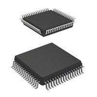
IC H8 MCU FLASH 16K 64QFP
Manufacturer
Renesas Electronics America
Series
H8® H8/300Lr
Datasheet
1.HD64F3644HV.pdf
(551 pages)
Specifications of HD64F3642AH
Core Processor
H8/300L
Core Size
8-Bit
Speed
8MHz
Connectivity
SCI
Peripherals
PWM, WDT
Number Of I /o
53
Program Memory Size
16KB (16K x 8)
Program Memory Type
FLASH
Ram Size
1K x 8
Voltage - Supply (vcc/vdd)
2.7 V ~ 5.5 V
Data Converters
A/D 8x8b
Oscillator Type
Internal
Operating Temperature
-20°C ~ 75°C
Package / Case
64-QFP
Lead Free Status / RoHS Status
Contains lead / RoHS non-compliant
Eeprom Size
-
Available stocks
Company
Part Number
Manufacturer
Quantity
Price
Company:

Part Number:
HD64F3642AH
Manufacturer:
HITACHI
Quantity:
12
Company:
Part Number:
HD64F3642AH
Manufacturer:
HITACHI
Quantity:
648
Company:
Part Number:
HD64F3642AH
Manufacturer:
Renesas Electronics America
Quantity:
10 000
Company:
Part Number:
HD64F3642AHV
Manufacturer:
RENESAS
Quantity:
1 000
Company:
Part Number:
HD64F3642AHV
Manufacturer:
Renesas Electronics America
Quantity:
10 000
Company:
Part Number:
HD64F3642AHV H8/3642A
Manufacturer:
RENESAS
Quantity:
190


Section 9 Timers
Rev. 6.00 Sep 12, 2006 page 260 of 526
REJ09B0326-0600
FTIA
Input capture
signal
FRC
ICRA
ICRC
Buffered input capture timing
Input capture can be buffered by using ICRC or ICRD as a buffer for ICRA or ICRB.
Figure 9.26 shows the timing when ICRA is buffered by ICRC (BUFEA = 1) and both
the rising and falling edges are selected (IEDGA = 1 and IEDGC = 0, or IEDGA = 0 and
IEDGC = 1).
When ICRC or ICRD is used as a buffer register, the input capture flag is still set by the
selected edge of the input capture input signal. For example, if ICRC is used to buffer ICRA,
when the edge transition selected by the IEDGC bit occurs at the input capture pin, ICFC will
be set, and if the ICIEC bit is set, an interrupt will be requested. The FRC value will not be
transferred to ICRC, however.
In buffered operation, if the upper byte of one of the two registers that receives a data transfer
(ICRA and ICRC, or ICRB and ICRD) is being read when an input capture signal would
normally occur, the input capture signal will be delayed by one system clock ( ). Figure 9.27
shows the case when BUFEA = 1.
Figure 9.26 Buffered Input Capture Timing (Normal Case)
M
m
n
M
n
n + 1
N
M
n
N
n
N + 1
Related parts for HD64F3642AH
Image
Part Number
Description
Manufacturer
Datasheet
Request
R

Part Number:
Description:
(HD64 Series) Hitachi Single-Chip Microcomputer
Manufacturer:
Hitachi Semiconductor
Datasheet:

Part Number:
Description:
KIT STARTER FOR M16C/29
Manufacturer:
Renesas Electronics America
Datasheet:

Part Number:
Description:
KIT STARTER FOR R8C/2D
Manufacturer:
Renesas Electronics America
Datasheet:

Part Number:
Description:
R0K33062P STARTER KIT
Manufacturer:
Renesas Electronics America
Datasheet:

Part Number:
Description:
KIT STARTER FOR R8C/23 E8A
Manufacturer:
Renesas Electronics America
Datasheet:

Part Number:
Description:
KIT STARTER FOR R8C/25
Manufacturer:
Renesas Electronics America
Datasheet:

Part Number:
Description:
KIT STARTER H8S2456 SHARPE DSPLY
Manufacturer:
Renesas Electronics America
Datasheet:

Part Number:
Description:
KIT STARTER FOR R8C38C
Manufacturer:
Renesas Electronics America
Datasheet:

Part Number:
Description:
KIT STARTER FOR R8C35C
Manufacturer:
Renesas Electronics America
Datasheet:

Part Number:
Description:
KIT STARTER FOR R8CL3AC+LCD APPS
Manufacturer:
Renesas Electronics America
Datasheet:
Part Number:
Description:
KIT STARTER FOR RX610
Manufacturer:
Renesas Electronics America
Datasheet:

Part Number:
Description:
KIT STARTER FOR R32C/118
Manufacturer:
Renesas Electronics America
Datasheet:

Part Number:
Description:
KIT DEV RSK-R8C/26-29
Manufacturer:
Renesas Electronics America
Datasheet:

Part Number:
Description:
KIT STARTER FOR SH7124
Manufacturer:
Renesas Electronics America
Datasheet:

Part Number:
Description:
KIT STARTER FOR H8SX/1622
Manufacturer:
Renesas Electronics America
Datasheet: