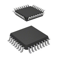
HD64F36912GFH Renesas Electronics America, HD64F36912GFH Datasheet - Page 113

HD64F36912GFH
Manufacturer Part Number
HD64F36912GFH
Description
IC H8 MCU FLASH 8K 32-QFP
Manufacturer
Renesas Electronics America
Series
H8® H8/300H Tinyr
Datasheet
1.DF36912GFHV.pdf
(442 pages)
Specifications of HD64F36912GFH
Core Processor
H8/300H
Core Size
16-Bit
Speed
12MHz
Connectivity
I²C, SCI
Peripherals
LVD, POR, PWM, WDT
Number Of I /o
18
Program Memory Size
8KB (8K x 8)
Program Memory Type
FLASH
Ram Size
1.5K x 8
Voltage - Supply (vcc/vdd)
3 V ~ 5.5 V
Data Converters
A/D 4x10b
Oscillator Type
Internal
Operating Temperature
-20°C ~ 75°C
Package / Case
32-LQFP
Lead Free Status / RoHS Status
Contains lead / RoHS non-compliant
Eeprom Size
-
Available stocks
Company
Part Number
Manufacturer
Quantity
Price
Company:
Part Number:
HD64F36912GFH
Manufacturer:
Renesas Electronics America
Quantity:
10 000
- Current page: 113 of 442
- Download datasheet (3Mb)
5.5.2
Figure 5.11 shows an example of connecting a ceramic resonator.
5.5.3
To use the external clock, input the external clock on pin OSC1. Figure 5.12 shows an example of
connection. The duty cycle of the external clock signal must be 45 to 55%.
5.6
5.6.1
Prescaler S is a 13-bit counter using the system clock ( ) as its input clock. The outputs, which are
divided clocks, are used as internal clocks by the on-chip peripheral modules. Prescaler S is
initialized to H'0000 by a reset, and starts counting on exit from the reset state. In standby mode
and subsleep mode, the system clock pulse generator stops. Prescaler S also stops and is initialized
to H'0000. It cannot be read from or written to by the CPU.
The outputs from prescaler S is shared by the on-chip peripheral modules. The division ratio can
be set separately for each on-chip peripheral module. In active mode and sleep mode, the clock
input to prescaler S is a system clock with the division ratio specified by bits MA2 to MA0 in
SYSCR2.
Connecting Ceramic Resonator
External Clock Input Method
Prescaler
Prescaler S
Figure 5.11 Example of Connection to Ceramic Resonator
PC1/OSC2/CLKOUT
PC1/OSC2/CLKOUT
Figure 5.12 Example of External Clock Input
PC0/OSC1
PC0/OSC1
General port
C
C
1
2
Rev. 3.00 Sep. 14, 2006 Page 83 of 408
C = C = 5 to 30 pF
External clock input
1
Section 5 Clock Pulse Generators
2
REJ09B0105-0300
Related parts for HD64F36912GFH
Image
Part Number
Description
Manufacturer
Datasheet
Request
R

Part Number:
Description:
KIT STARTER FOR M16C/29
Manufacturer:
Renesas Electronics America
Datasheet:

Part Number:
Description:
KIT STARTER FOR R8C/2D
Manufacturer:
Renesas Electronics America
Datasheet:

Part Number:
Description:
R0K33062P STARTER KIT
Manufacturer:
Renesas Electronics America
Datasheet:

Part Number:
Description:
KIT STARTER FOR R8C/23 E8A
Manufacturer:
Renesas Electronics America
Datasheet:

Part Number:
Description:
KIT STARTER FOR R8C/25
Manufacturer:
Renesas Electronics America
Datasheet:

Part Number:
Description:
KIT STARTER H8S2456 SHARPE DSPLY
Manufacturer:
Renesas Electronics America
Datasheet:

Part Number:
Description:
KIT STARTER FOR R8C38C
Manufacturer:
Renesas Electronics America
Datasheet:

Part Number:
Description:
KIT STARTER FOR R8C35C
Manufacturer:
Renesas Electronics America
Datasheet:

Part Number:
Description:
KIT STARTER FOR R8CL3AC+LCD APPS
Manufacturer:
Renesas Electronics America
Datasheet:

Part Number:
Description:
KIT STARTER FOR RX610
Manufacturer:
Renesas Electronics America
Datasheet:

Part Number:
Description:
KIT STARTER FOR R32C/118
Manufacturer:
Renesas Electronics America
Datasheet:

Part Number:
Description:
KIT DEV RSK-R8C/26-29
Manufacturer:
Renesas Electronics America
Datasheet:

Part Number:
Description:
KIT STARTER FOR SH7124
Manufacturer:
Renesas Electronics America
Datasheet:

Part Number:
Description:
KIT STARTER FOR H8SX/1622
Manufacturer:
Renesas Electronics America
Datasheet:


