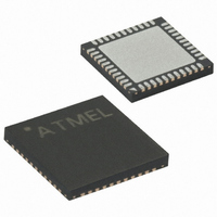
ATMEGA644V-10MU Atmel, ATMEGA644V-10MU Datasheet - Page 224

ATMEGA644V-10MU
Manufacturer Part Number
ATMEGA644V-10MU
Description
IC AVR MCU FLASH 64K 44-QFN
Manufacturer
Atmel
Series
AVR® ATmegar
Specifications of ATMEGA644V-10MU
Core Processor
AVR
Core Size
8-Bit
Speed
10MHz
Connectivity
I²C, SPI, UART/USART
Peripherals
Brown-out Detect/Reset, POR, PWM, WDT
Number Of I /o
32
Program Memory Size
64KB (32K x 16)
Program Memory Type
FLASH
Eeprom Size
2K x 8
Ram Size
4K x 8
Voltage - Supply (vcc/vdd)
1.8 V ~ 5.5 V
Data Converters
A/D 8x10b
Oscillator Type
Internal
Operating Temperature
-40°C ~ 85°C
Package / Case
44-VQFN Exposed Pad
Package
44QFN EP
Device Core
AVR
Family Name
ATmega
Maximum Speed
10 MHz
Operating Supply Voltage
2.5|3.3|5 V
Data Bus Width
8 Bit
Number Of Programmable I/os
32
Interface Type
JTAG/SPI/TWI/USART
On-chip Adc
8-chx10-bit
Number Of Timers
3
Processor Series
ATMEGA64x
Core
AVR8
Data Ram Size
4 KB
Maximum Clock Frequency
20 MHz
Maximum Operating Temperature
+ 85 C
Mounting Style
SMD/SMT
Minimum Operating Temperature
- 40 C
For Use With
ATSTK600-TQFP44 - STK600 SOCKET/ADAPTER 44-TQFPATSTK600 - DEV KIT FOR AVR/AVR32770-1007 - ISP 4PORT ATMEL AVR MCU SPI/JTAGATAVRISP2 - PROGRAMMER AVR IN SYSTEM
Lead Free Status / RoHS Status
Lead free / RoHS Compliant
Available stocks
Company
Part Number
Manufacturer
Quantity
Price
Part Number:
ATMEGA644V-10MU
Manufacturer:
ATMEL/爱特梅尔
Quantity:
20 000
- Current page: 224 of 376
- Download datasheet (8Mb)
19.8
224
Multi-master Systems and Arbitration
ATmega644
Note that data is transmitted both from Master to Slave and vice versa. The Master must instruct
the Slave what location it wants to read, requiring the use of the MT mode. Subsequently, data
must be read from the Slave, implying the use of the MR mode. Thus, the transfer direction must
be changed. The Master must keep control of the bus during all these steps, and the steps
should be carried out as an atomical operation. If this principle is violated in a multimaster sys-
tem, another Master can alter the data pointer in the EEPROM between steps 2 and 3, and the
Master will read the wrong data location. Such a change in transfer direction is accomplished by
transmitting a REPEATED START between the transmission of the address byte and reception
of the data. After a REPEATED START, the Master keeps ownership of the bus. The following
figure shows the flow in this transfer.
Figure 19-19. Combining Several TWI Modes to Access a Serial EEPROM
If multiple masters are connected to the same bus, transmissions may be initiated simultane-
ously by one or more of them. The TWI standard ensures that such situations are handled in
such a way that one of the masters will be allowed to proceed with the transfer, and that no data
will be lost in the process. An example of an arbitration situation is depicted below, where two
masters are trying to transmit data to a Slave Receiver.
Figure 19-20. An Arbitration Example
Several different scenarios may arise during arbitration, as described below:
• Two or more masters are performing identical communication with the same Slave. In this
• Two or more masters are accessing the same Slave with different data or direction bit. In this
case, neither the Slave nor any of the masters will know about the bus contention.
case, arbitration will occur, either in the READ/WRITE bit or in the data bits. The masters trying
to output a one on SDA while another Master outputs a zero will lose the arbitration. Losing
masters will switch to not addressed Slave mode or wait until the bus is free and transmit a new
START condition, depending on application software action.
S
S = START
SDA
SCL
Transmitted from master to slave
SLA+W
TRANSMITTER
Device 1
MASTER
A
Master Transmitter
ADDRESS
TRANSMITTER
Device 2
MASTER
Device 3
A
RECEIVER
SLAVE
Rs = REPEATED START
Rs
Transmitted from slave to master
........
SLA+R
Device n
V
CC
A
Master Receiver
R1
DATA
R2
P = STOP
2593N–AVR–07/10
A
P
Related parts for ATMEGA644V-10MU
Image
Part Number
Description
Manufacturer
Datasheet
Request
R

Part Number:
Description:
Manufacturer:
Atmel Corporation
Datasheet:

Part Number:
Description:
IC AVR MCU FLASH 64K 44-QFN
Manufacturer:
Atmel
Datasheet:

Part Number:
Description:
IC AVR MCU FLASH 64K 44TQFP
Manufacturer:
Atmel
Datasheet:

Part Number:
Description:
IC AVR MCU FLASH 64K 40DIP
Manufacturer:
Atmel
Datasheet:

Part Number:
Description:
MCU AVR 64K FLASH 20MHZ 44TQFP
Manufacturer:
Atmel
Datasheet:

Part Number:
Description:
MCU AVR 64K FLASH 20MHZ 44QFN
Manufacturer:
Atmel
Datasheet:

Part Number:
Description:
Atmega644 8-bit Avr Microcontroller With 64k Bytes In-system Programmable Flash
Manufacturer:
ATMEL Corporation
Datasheet:

Part Number:
Description:
Manufacturer:
Atmel Corporation
Datasheet:

Part Number:
Description:
Manufacturer:
ATMEL Corporation
Datasheet:

Part Number:
Description:
Manufacturer:
ATMEL Corporation
Datasheet:

Part Number:
Description:
IC AVR MCU 64K 16MHZ 5V 64TQFP
Manufacturer:
Atmel
Datasheet:

Part Number:
Description:
IC AVR MCU 64K 16MHZ 5V 64-QFN
Manufacturer:
Atmel
Datasheet:


