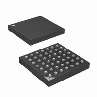
ATXMEGA16A4-CU Atmel, ATXMEGA16A4-CU Datasheet - Page 69

ATXMEGA16A4-CU
Manufacturer Part Number
ATXMEGA16A4-CU
Description
MCU AVR 16+4KB FLASH 49VFBGA
Manufacturer
Atmel
Series
AVR® XMEGAr
Specifications of ATXMEGA16A4-CU
Core Processor
AVR
Core Size
8/16-Bit
Speed
32MHz
Connectivity
I²C, IrDA, SPI, UART/USART
Peripherals
Brown-out Detect/Reset, DMA, POR, PWM, WDT
Number Of I /o
34
Program Memory Size
16KB (8K x 16)
Program Memory Type
FLASH
Eeprom Size
1K x 8
Ram Size
2K x 8
Voltage - Supply (vcc/vdd)
1.6 V ~ 3.6 V
Data Converters
A/D 12x12b, D/A 2x12b
Oscillator Type
Internal
Operating Temperature
-40°C ~ 85°C
Package / Case
49-VFBGA
Processor Series
ATXMEGA16x
Core
AVR8
Data Bus Width
8 bit, 16 bit
Data Ram Size
2 KB
Interface Type
I2C/SPI/USART
Maximum Clock Frequency
32 MHz
Number Of Programmable I/os
34
Number Of Timers
5
Operating Supply Voltage
1.6 V to 3.6 V
Maximum Operating Temperature
+ 85 C
Mounting Style
SMD/SMT
3rd Party Development Tools
EWAVR, EWAVR-BL
Development Tools By Supplier
ATAVRDRAGON, ATAVRISP2, ATAVRONEKIT
Minimum Operating Temperature
- 40 C
On-chip Adc
12-ch x 12-bit
On-chip Dac
2-ch x 12-bit
For Use With
ATAVRONEKIT - KIT AVR/AVR32 DEBUGGER/PROGRMMRATSTK600 - DEV KIT FOR AVR/AVR32770-1007 - ISP 4PORT ATMEL AVR MCU SPI/JTAG770-1004 - ISP 4PORT FOR ATMEL AVR MCU SPI
Lead Free Status / RoHS Status
Lead free / RoHS Compliant
Available stocks
Company
Part Number
Manufacturer
Quantity
Price
- Current page: 69 of 445
- Download datasheet (6Mb)
6.5
6.6
6.7
6.7.1
8077H–AVR–12/09
Event Timing
Filtering
Quadrature Decoder
Quadrature Operation
An event normally lasts for one peripheral clock cycle, but some event sources, such as low
level on an I/O pin, will generate events continuously. Details on this are described in the
datasheet for each peripheral, but unless stated, an event lasts for one peripheral clock cycle
only.
It takes maximum two clock cycles from an event is generated until the event actions in other
peripherals is triggered. It takes one clock cycle from the event happens until it is registered by
the event routing network on the first positive clock edge. It takes an additional clock cycle to
route the event through the event channel to the event user.
Each event channel includes a digital filter. When this is enabled for an event channel, an event
must be sampled with the same value for configurable number of system clock cycles before it is
accepted. This is primarily intended for pin change events.
The Event System includes three Quadrature Decoders (QDECs). This enables the Event Sys-
tem to decode quadrature input on I/O pins, and send data events that a Timer/Counter can
decode to trigger the appropriate event action: count up, count down or index/reset.
on page 69
decoded, and how they can be generated. The QDECs and related features, control and status
register are available for event channel 0, 2 and 4.
Table 6-2.
A quadrature signal is characterized by having two square waves phase shifted 90 degrees rela-
tive to each other. Rotational movement can be measured by counting the edges of the two
waveforms. The phase relationship between the two square waves determines the direction of
rotation.
STROBE
0
0
1
1
summarizes which quadrature decoder data events are available, how they are
DATA
Quadrature Decoder Data Events
0
1
0
1
Data Event User
No Event
Index/Reset
Count Down
Count Up
Signaling Event User
No Event
Signaling Event
Signaling Event
No Event
XMEGA A
Table 6-2
69
Related parts for ATXMEGA16A4-CU
Image
Part Number
Description
Manufacturer
Datasheet
Request
R

Part Number:
Description:
DEV KIT FOR AVR/AVR32
Manufacturer:
Atmel
Datasheet:

Part Number:
Description:
INTERVAL AND WIPE/WASH WIPER CONTROL IC WITH DELAY
Manufacturer:
ATMEL Corporation
Datasheet:

Part Number:
Description:
Low-Voltage Voice-Switched IC for Hands-Free Operation
Manufacturer:
ATMEL Corporation
Datasheet:

Part Number:
Description:
MONOLITHIC INTEGRATED FEATUREPHONE CIRCUIT
Manufacturer:
ATMEL Corporation
Datasheet:

Part Number:
Description:
AM-FM Receiver IC U4255BM-M
Manufacturer:
ATMEL Corporation
Datasheet:

Part Number:
Description:
Monolithic Integrated Feature Phone Circuit
Manufacturer:
ATMEL Corporation
Datasheet:

Part Number:
Description:
Multistandard Video-IF and Quasi Parallel Sound Processing
Manufacturer:
ATMEL Corporation
Datasheet:

Part Number:
Description:
High-performance EE PLD
Manufacturer:
ATMEL Corporation
Datasheet:

Part Number:
Description:
8-bit Flash Microcontroller
Manufacturer:
ATMEL Corporation
Datasheet:

Part Number:
Description:
2-Wire Serial EEPROM
Manufacturer:
ATMEL Corporation
Datasheet:


