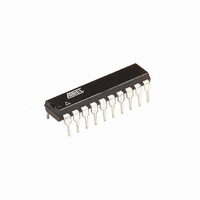
ATTINY26-16PU Atmel, ATTINY26-16PU Datasheet - Page 179

ATTINY26-16PU
Manufacturer Part Number
ATTINY26-16PU
Description
IC AVR MCU 2K 16MHZ IND 20-DIP
Manufacturer
Atmel
Series
AVR® ATtinyr
Specifications of ATTINY26-16PU
Core Processor
AVR
Core Size
8-Bit
Speed
16MHz
Connectivity
USI
Peripherals
Brown-out Detect/Reset, POR, PWM, WDT
Number Of I /o
16
Program Memory Size
2KB (1K x 16)
Program Memory Type
FLASH
Eeprom Size
128 x 8
Ram Size
128 x 8
Voltage - Supply (vcc/vdd)
4.5 V ~ 5.5 V
Data Converters
A/D 11x10b
Oscillator Type
Internal
Operating Temperature
-40°C ~ 85°C
Package / Case
20-DIP (0.300", 7.62mm)
Processor Series
ATTINY2x
Core
AVR8
Data Bus Width
8 bit
Data Ram Size
128 B
Interface Type
2-Wire/ISP/SM-Bus/SPI/UART/USI
Maximum Clock Frequency
16 MHz
Number Of Programmable I/os
16
Number Of Timers
2
Operating Supply Voltage
4.5 V to 5.5 V
Maximum Operating Temperature
+ 85 C
Mounting Style
Through Hole
3rd Party Development Tools
EWAVR, EWAVR-BL
Development Tools By Supplier
ATAVRDRAGON, ATSTK500, ATSTK600, ATAVRISP2, ATAVRONEKIT
Minimum Operating Temperature
- 40 C
On-chip Adc
11-ch x 10-bit
Package
20PDIP
Device Core
AVR
Family Name
ATtiny
Maximum Speed
16 MHz
For Use With
ATSTK600 - DEV KIT FOR AVR/AVR32770-1007 - ISP 4PORT ATMEL AVR MCU SPI/JTAGATAVRISP2 - PROGRAMMER AVR IN SYSTEMATSTK505 - ADAPTER KIT FOR 14PIN AVR MCU
Lead Free Status / RoHS Status
Lead free / RoHS Compliant
Table of
Contents
1477K–AVR–08/10
Features................................................................................................ 1
Pin Configuration ................................................................................ 2
Description........................................................................................... 3
General Information ............................................................................ 6
AVR CPU Core ..................................................................................... 7
Memories............................................................................................ 16
System Clock and Clock Options .................................................... 23
System Control and Reset................................................................ 32
Power Management and Sleep Modes ............................................ 37
Pin Descriptions.................................................................................................... 5
Resources ............................................................................................................ 6
Code Examples .................................................................................................... 6
Architectural Overview.......................................................................................... 7
General Purpose Register File ............................................................................. 8
ALU – Arithmetic Logic Unit.................................................................................. 9
Status Register – SREG ..................................................................................... 10
Stack Pointer – SP ............................................................................................. 11
Program and Data Addressing Modes ............................................................... 11
In-System Programmable Flash Program Memory ............................................ 17
SRAM Data Memory........................................................................................... 17
EEPROM Data Memory ..................................................................................... 18
I/O Memory ......................................................................................................... 20
Clock Systems and their Distribution .................................................................. 23
Clock Sources .................................................................................................... 25
Default Clock Source .......................................................................................... 26
Crystal Oscillator ................................................................................................ 26
Low-frequency Crystal Oscillator ........................................................................ 27
External RC Oscillator ........................................................................................ 28
Calibrated Internal RC Oscillator ........................................................................ 29
External Clock .................................................................................................... 30
High Frequency PLL Clock – PLLCLK ............................................................... 31
Power-on Reset .................................................................................................. 33
External Reset .................................................................................................... 34
Brown-out Detection ........................................................................................... 35
Watchdog Reset ................................................................................................. 35
MCU Status Register – MCUSR......................................................................... 36
MCU Control Register – MCUCR ....................................................................... 37
Block Diagram ...................................................................................................... 4
i


