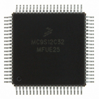
MC9S12C32MFUE25 Freescale Semiconductor, MC9S12C32MFUE25 Datasheet - Page 364

MC9S12C32MFUE25
Manufacturer Part Number
MC9S12C32MFUE25
Description
IC MCU 32K FLASH 25MHZ 80-QFP
Manufacturer
Freescale Semiconductor
Series
HCS12r
Datasheets
1.MC9S12GC16MFUE.pdf
(690 pages)
2.MC9S12C96CFUER.pdf
(26 pages)
3.MC9S12C32CFAE25.pdf
(2 pages)
Specifications of MC9S12C32MFUE25
Core Processor
HCS12
Core Size
16-Bit
Speed
25MHz
Connectivity
CAN, EBI/EMI, SCI, SPI
Peripherals
POR, PWM, WDT
Number Of I /o
60
Program Memory Size
32KB (32K x 8)
Program Memory Type
FLASH
Ram Size
2K x 8
Voltage - Supply (vcc/vdd)
2.35 V ~ 5.5 V
Data Converters
A/D 8x10b
Oscillator Type
Internal
Operating Temperature
-40°C ~ 125°C
Package / Case
80-QFP
Processor Series
S12C
Core
HCS12
Data Bus Width
16 bit
Data Ram Size
2 KB
Interface Type
CAN/SCI/SPI
Maximum Clock Frequency
25 MHz
Number Of Programmable I/os
60
Number Of Timers
8
Operating Supply Voltage
3.3 V to 5.5 V
Maximum Operating Temperature
+ 125 C
Mounting Style
SMD/SMT
3rd Party Development Tools
EWHCS12
Development Tools By Supplier
M68EVB912C32EE
Minimum Operating Temperature
- 40 C
On-chip Adc
8-ch x 10-bit
For Use With
CML12C32SLK - KIT STUDENT LEARNING 16BIT HCS12
Lead Free Status / RoHS Status
Lead free / RoHS Compliant
Eeprom Size
-
Lead Free Status / Rohs Status
Lead free / RoHS Compliant
Available stocks
Company
Part Number
Manufacturer
Quantity
Price
Company:
Part Number:
MC9S12C32MFUE25
Manufacturer:
Freescale Semiconductor
Quantity:
10 000
Part Number:
MC9S12C32MFUE25
Manufacturer:
FREESCALE
Quantity:
20 000
Company:
Part Number:
MC9S12C32MFUE25R
Manufacturer:
Freescale Semiconductor
Quantity:
10 000
- Current page: 364 of 690
- Download datasheet (4Mb)
Chapter 12 Pulse-Width Modulator (PWM8B6CV1) Block Description
12.3.2.12 PWM Channel Counter Registers (PWMCNTx)
Each channel has a dedicated 8-bit up/down counter which runs at the rate of the selected clock source.
The counter can be read at any time without affecting the count or the operation of the PWM channel. In
left aligned output mode, the counter counts from 0 to the value in the period register – 1. In center aligned
output mode, the counter counts from 0 up to the value in the period register and then back down to 0.
Any value written to the counter causes the counter to reset to 0x0000, the counter direction to be set to
up, the immediate load of both duty and period registers with values from the buffers, and the output to
change according to the polarity bit. The counter is also cleared at the end of the effective period (see
Section 12.4.2.5, “Left Aligned Outputs,”
details). When the channel is disabled (PWMEx = 0), the PWMCNTx register does not count. When a
channel becomes enabled (PWMEx = 1), the associated PWM counter starts at the count in the
PWMCNTx register. For more detailed information on the operation of the counters, reference
Section 12.4.2.4, “PWM Timer Counters.”
In concatenated mode, writes to the 16-bit counter by using a 16-bit access or writes to either the low- or
high-order byte of the counter will reset the 16-bit counter. Reads of the 16-bit counter must be made by
16-bit access to maintain data coherency.
364
Module Base + 0x000C
Module Base + 0x000D
Reset
Reset
W
W
R
R
Bit 7
Bit 7
0
0
0
0
7
7
Writing to the counter while the channel is enabled can cause an irregular
PWM cycle to occur.
Figure 12-15. PWM Channel Counter Registers (PWMCNT0)
Figure 12-16. PWM Channel Counter Registers (PWMCNT1)
6
0
0
6
0
0
6
6
MC9S12C-Family / MC9S12GC-Family
5
0
0
5
0
0
5
5
and
Section 12.4.2.6, “Center Aligned Outputs,”
Rev 01.24
NOTE
4
0
0
4
0
0
4
4
3
0
0
3
0
0
3
3
2
0
0
2
0
0
2
2
Freescale Semiconductor
1
0
0
1
0
0
1
1
for more
Bit 0
Bit 0
0
0
0
0
0
0
Related parts for MC9S12C32MFUE25
Image
Part Number
Description
Manufacturer
Datasheet
Request
R
Part Number:
Description:
Manufacturer:
Freescale Semiconductor, Inc
Datasheet:
Part Number:
Description:
Manufacturer:
Freescale Semiconductor, Inc
Datasheet:
Part Number:
Description:
Manufacturer:
Freescale Semiconductor, Inc
Datasheet:
Part Number:
Description:
Manufacturer:
Freescale Semiconductor, Inc
Datasheet:
Part Number:
Description:
Manufacturer:
Freescale Semiconductor, Inc
Datasheet:
Part Number:
Description:
Manufacturer:
Freescale Semiconductor, Inc
Datasheet:
Part Number:
Description:
Manufacturer:
Freescale Semiconductor, Inc
Datasheet:
Part Number:
Description:
Manufacturer:
Freescale Semiconductor, Inc
Datasheet:
Part Number:
Description:
Manufacturer:
Freescale Semiconductor, Inc
Datasheet:
Part Number:
Description:
Manufacturer:
Freescale Semiconductor, Inc
Datasheet:
Part Number:
Description:
Manufacturer:
Freescale Semiconductor, Inc
Datasheet:
Part Number:
Description:
Manufacturer:
Freescale Semiconductor, Inc
Datasheet:
Part Number:
Description:
Manufacturer:
Freescale Semiconductor, Inc
Datasheet:
Part Number:
Description:
Manufacturer:
Freescale Semiconductor, Inc
Datasheet:
Part Number:
Description:
Manufacturer:
Freescale Semiconductor, Inc
Datasheet:


