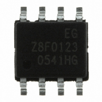
Z8F0123SB005EG Zilog, Z8F0123SB005EG Datasheet - Page 95

Z8F0123SB005EG
Manufacturer Part Number
Z8F0123SB005EG
Description
IC ENCORE MCU FLASH 1K 8SOIC
Manufacturer
Zilog
Series
Encore!® XP®r
Datasheet
1.Z8F0223SB005SG.pdf
(247 pages)
Specifications of Z8F0123SB005EG
Core Processor
Z8
Core Size
8-Bit
Speed
5MHz
Connectivity
IrDA, UART/USART
Peripherals
Brown-out Detect/Reset, LED, POR, PWM, WDT
Number Of I /o
6
Program Memory Size
1KB (1K x 8)
Program Memory Type
FLASH
Ram Size
256 x 8
Voltage - Supply (vcc/vdd)
2.7 V ~ 3.6 V
Data Converters
A/D 4x10b
Oscillator Type
Internal
Operating Temperature
-40°C ~ 105°C
Package / Case
8-SOIC (3.9mm Width)
Lead Free Status / RoHS Status
Lead free / RoHS Compliant
Eeprom Size
-
Other names
269-3757
- Current page: 95 of 247
- Download datasheet (4Mb)
PS024314-0308
Caution:
CAPTURE/COMPARE Mode
PWM DUAL OUTPUT Mode
CAPTURE RESTART Mode
COMPARATOR COUNTER Mode
PRES—Prescale value.
The timer input clock is divided by 2
prescaler is reset each time the Timer is disabled. This reset ensures proper clock division
each time the Timer is restarted.
When the Timer Output alternate function TxOUT on a GPIO port pin is enabled, Tx-
OUT changes to whatever state the
for that to happen. Also, the port data direction sub register is not needed to be set to
output on TxOUT. Changing the
immediately change the TxOUT.
0 = Counting is started on the first rising edge of the Timer Input signal. The current
count is captured on subsequent rising edges of the Timer Input signal.
1 = Counting is started on the first falling edge of the Timer Input signal. The current
count is captured on subsequent falling edges of the Timer Input signal.
0 = Timer Output is forced Low (0) and Timer Output Complement is forced High (1)
when the timer is disabled. When enabled, the Timer Output is forced High (1) upon
PWM count match and forced Low (0) upon Reload. When enabled, the Timer Output
Complement is forced Low (0) upon PWM count match and forced High (1) upon
Reload. The PWMD field in TxCTL0 register is a programmable delay to control the
number of cycles time delay before the Timer Output and the Timer Output
Complement is forced to High (1).
1 = Timer Output is forced High (1) and Timer Output Complement is forced Low (0)
when the timer is disabled. When enabled, the Timer Output is forced Low (0) upon
PWM count match and forced High (1) upon Reload.When enabled, the Timer Output
Complement is forced High (1) upon PWM count match and forced Low (0) upon
Reload. The PWMD field in TxCTL0 register is a programmable delay to control the
number of cycles time delay before the Timer Output and the Timer Output
Complement is forced to Low (0).
0 = Count is captured on the rising edge of the Timer Input signal
1 = Count is captured on the falling edge of the Timer Input signal
When the timer is disabled, the Timer Output signal is set to the value of this bit.
When the timer is enabled, the Timer Output signal is complemented upon timer
Reload.
000 = Divide by 1
001 = Divide by 2
TPOL
PRES
TPOL
, where PRES can be set from 0 to 7. The
bit with the timer enabled and running does not
bit is in. The timer does not need to be enabled
Z8 Encore! XP
Product Specification
®
F0823 Series
Timers
85
Related parts for Z8F0123SB005EG
Image
Part Number
Description
Manufacturer
Datasheet
Request
R

Part Number:
Description:
Communication Controllers, ZILOG INTELLIGENT PERIPHERAL CONTROLLER (ZIP)
Manufacturer:
Zilog, Inc.
Datasheet:

Part Number:
Description:
KIT DEV FOR Z8 ENCORE 16K TO 64K
Manufacturer:
Zilog
Datasheet:

Part Number:
Description:
KIT DEV Z8 ENCORE XP 28-PIN
Manufacturer:
Zilog
Datasheet:

Part Number:
Description:
DEV KIT FOR Z8 ENCORE 8K/4K
Manufacturer:
Zilog
Datasheet:

Part Number:
Description:
KIT DEV Z8 ENCORE XP 28-PIN
Manufacturer:
Zilog
Datasheet:

Part Number:
Description:
DEV KIT FOR Z8 ENCORE 4K TO 8K
Manufacturer:
Zilog
Datasheet:

Part Number:
Description:
CMOS Z8 microcontroller. ROM 16 Kbytes, RAM 256 bytes, speed 16 MHz, 32 lines I/O, 3.0V to 5.5V
Manufacturer:
Zilog, Inc.
Datasheet:

Part Number:
Description:
Low-cost microcontroller. 512 bytes ROM, 61 bytes RAM, 8 MHz
Manufacturer:
Zilog, Inc.
Datasheet:

Part Number:
Description:
Z8 4K OTP Microcontroller
Manufacturer:
Zilog, Inc.
Datasheet:

Part Number:
Description:
CMOS SUPER8 ROMLESS MCU
Manufacturer:
Zilog, Inc.
Datasheet:

Part Number:
Description:
SL1866 CMOSZ8 OTP Microcontroller
Manufacturer:
Zilog, Inc.
Datasheet:

Part Number:
Description:
SL1866 CMOSZ8 OTP Microcontroller
Manufacturer:
Zilog, Inc.
Datasheet:

Part Number:
Description:
OTP (KB) = 1, RAM = 125, Speed = 12, I/O = 14, 8-bit Timers = 2, Comm Interfaces Other Features = Por, LV Protect, Voltage = 4.5-5.5V
Manufacturer:
Zilog, Inc.
Datasheet:

Part Number:
Description:
Manufacturer:
Zilog, Inc.
Datasheet:


