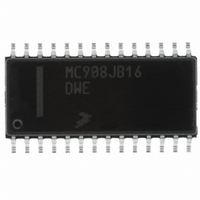
MC908JB16DWE Freescale Semiconductor, MC908JB16DWE Datasheet - Page 322

MC908JB16DWE
Manufacturer Part Number
MC908JB16DWE
Description
IC MCU 16K FLASH 6MHZ USB 28SOIC
Manufacturer
Freescale Semiconductor
Series
HC08r
Specifications of MC908JB16DWE
Core Processor
HC08
Core Size
8-Bit
Speed
6MHz
Connectivity
SCI, USB
Peripherals
LED, LVD, POR, PWM
Number Of I /o
21
Program Memory Size
16KB (16K x 8)
Program Memory Type
FLASH
Ram Size
384 x 8
Voltage - Supply (vcc/vdd)
4 V ~ 5.5 V
Oscillator Type
Internal
Operating Temperature
0°C ~ 70°C
Package / Case
28-SOIC (7.5mm Width)
Processor Series
HC08JB
Core
HC08
Data Bus Width
8 bit
Data Ram Size
384 B
Interface Type
I2C/SCI/SPI/USB
Maximum Clock Frequency
12 MHz
Number Of Programmable I/os
21
Number Of Timers
4
Operating Supply Voltage
5.5 V
Maximum Operating Temperature
+ 70 C
Mounting Style
SMD/SMT
Development Tools By Supplier
FSICEBASE, DEMO908GZ60E, M68EML08GZE, KITUSBSPIDGLEVME, KITUSBSPIEVME, KIT33810EKEVME
Minimum Operating Temperature
0 C
Controller Family/series
HC08
No. Of I/o's
21
Ram Memory Size
384Byte
Cpu Speed
8MHz
No. Of Timers
2
Embedded Interface Type
I2C, SCI, SPI
Rohs Compliant
Yes
Lead Free Status / RoHS Status
Lead free / RoHS Compliant
Eeprom Size
-
Data Converters
-
Lead Free Status / Rohs Status
Lead free / RoHS Compliant
Available stocks
Company
Part Number
Manufacturer
Quantity
Price
Company:
Part Number:
MC908JB16DWE
Manufacturer:
FREESCALE
Quantity:
1 831
Part Number:
MC908JB16DWE
Manufacturer:
FRE/MOT
Quantity:
20 000
- Current page: 322 of 332
- Download datasheet (4Mb)
Electrical Specifications
20.12 USB Signaling Levels
20.13 CGM Electrical Characteristics
Technical Data
322
Notes:
CGM power supply
CGM supply current
CGM regulator output voltage
CGM output high voltage
CGM output low voltage
CGM output equivalent
capacitance
CGM output rise and fall time
Output resistive load
Differential 1
Differential 0
Single-ended 0 (SE0)
Data J state (low speed)
Data K state (low speed)
Idle state (low speed)
Resume state
Start of packet (SOP)
End of packet (EOP)
Reset
1. The width of EOP is defined in bit times relative to the speed of transmission.
2. The width of EOP is defined in bit times relative to the device type receiving the EOP. The bit time is approximate.
Characteristic
Bus State
(1)
D+ > V
D– > V
D+ and D– < V
Differential 0
Differential 1
NA
Differential 1
Data lines switch from Idle to K State
SE0 for approximately 2 bit times
followed by a J state for 1 bit time
NA
Both PLLs enabled
One PLL enabled
(I
(I
Load
Load
10% to 90%
Condition
C
R
L
L
OH
OH
= –2.0 mA)
= 1.6 mA)
= 10pF
= 2kΩ
(min) and D– < V
(min) and D– < V
Electrical Specifications
Transmit
OL
(max)
Symbol
V
C
V
REGA0
I
t
V
V
DDA
R
R
DDA
OUT
OH
OL
/t
L
OL
OL
F
(max)
Signaling Levels
(max)
(1)
V
REGA0
Min
4.0
2.9
—
—
—
—
—
2
(D+) – (D–) > 200 mV
(D–) – (D+) > 200 mV
D+ and D– < V
Differential 0
Differential 1
D– > V
Differential 1
SE0 for ≥ 1 bit time
J state for 1 bit time
D+ and D– < V
–0.8
IHZ
Typ
(min) and D+ < V
3.3
MC68HC908JB16
—
—
—
—
—
5
6
3
(2)
Freescale Semiconductor
Receive
IL
IL
(max)
(max) for ≥ 8µs
(2)
Max
followed by a
5.5
3.7
0.4
10
12
—
—
5
8
IL
—
(max)
Rev. 1.1
Unit
mA
mA
kΩ
pF
ns
V
V
V
V
Related parts for MC908JB16DWE
Image
Part Number
Description
Manufacturer
Datasheet
Request
R
Part Number:
Description:
Manufacturer:
Freescale Semiconductor, Inc
Datasheet:
Part Number:
Description:
Manufacturer:
Freescale Semiconductor, Inc
Datasheet:
Part Number:
Description:
Manufacturer:
Freescale Semiconductor, Inc
Datasheet:
Part Number:
Description:
Manufacturer:
Freescale Semiconductor, Inc
Datasheet:
Part Number:
Description:
Manufacturer:
Freescale Semiconductor, Inc
Datasheet:
Part Number:
Description:
Manufacturer:
Freescale Semiconductor, Inc
Datasheet:
Part Number:
Description:
Manufacturer:
Freescale Semiconductor, Inc
Datasheet:
Part Number:
Description:
Manufacturer:
Freescale Semiconductor, Inc
Datasheet:
Part Number:
Description:
Manufacturer:
Freescale Semiconductor, Inc
Datasheet:
Part Number:
Description:
Manufacturer:
Freescale Semiconductor, Inc
Datasheet:
Part Number:
Description:
Manufacturer:
Freescale Semiconductor, Inc
Datasheet:
Part Number:
Description:
Manufacturer:
Freescale Semiconductor, Inc
Datasheet:
Part Number:
Description:
Manufacturer:
Freescale Semiconductor, Inc
Datasheet:
Part Number:
Description:
Manufacturer:
Freescale Semiconductor, Inc
Datasheet:
Part Number:
Description:
Manufacturer:
Freescale Semiconductor, Inc
Datasheet:


