MC908JB16DWE Freescale Semiconductor, MC908JB16DWE Datasheet - Page 255
MC908JB16DWE
Manufacturer Part Number
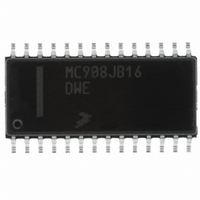
MC908JB16DWE
Description
IC MCU 16K FLASH 6MHZ USB 28SOIC
Manufacturer
Freescale Semiconductor
Series
HC08r
Specifications of MC908JB16DWE
Core Processor
HC08
Core Size
8-Bit
Speed
6MHz
Connectivity
SCI, USB
Peripherals
LED, LVD, POR, PWM
Number Of I /o
21
Program Memory Size
16KB (16K x 8)
Program Memory Type
FLASH
Ram Size
384 x 8
Voltage - Supply (vcc/vdd)
4 V ~ 5.5 V
Oscillator Type
Internal
Operating Temperature
0°C ~ 70°C
Package / Case
28-SOIC (7.5mm Width)
Processor Series
HC08JB
Core
HC08
Data Bus Width
8 bit
Data Ram Size
384 B
Interface Type
I2C/SCI/SPI/USB
Maximum Clock Frequency
12 MHz
Number Of Programmable I/os
21
Number Of Timers
4
Operating Supply Voltage
5.5 V
Maximum Operating Temperature
+ 70 C
Mounting Style
SMD/SMT
Development Tools By Supplier
FSICEBASE, DEMO908GZ60E, M68EML08GZE, KITUSBSPIDGLEVME, KITUSBSPIEVME, KIT33810EKEVME
Minimum Operating Temperature
0 C
Controller Family/series
HC08
No. Of I/o's
21
Ram Memory Size
384Byte
Cpu Speed
8MHz
No. Of Timers
2
Embedded Interface Type
I2C, SCI, SPI
Rohs Compliant
Yes
Lead Free Status / RoHS Status
Lead free / RoHS Compliant
Eeprom Size
-
Data Converters
-
Lead Free Status / Rohs Status
Lead free / RoHS Compliant
Available stocks
Company
Part Number
Manufacturer
Quantity
Price
Company:

Part Number:
MC908JB16DWE
Manufacturer:
FREESCALE
Quantity:
1 831
Part Number:
MC908JB16DWE
Manufacturer:
FRE/MOT
Quantity:
20 000


13.8 Programming the PLL
13.9 CGM I/O Registers
MC68HC908JB16
Freescale Semiconductor
NOTE:
—
Rev. 1.1
With the PLLs off (PLLON = 0), use the following procedure to initialize
both PLLs:
Then for each PLL, use the following procedure to program the VCO and
reference dividers:
To reprogram the PLL frequency, clear the PLLON bit (PLLON =0) and
repeat steps 3 to 6.
Do not program both PLLs to the same frequency. A difference of 50kHz
or more is recommended between the two PLL outputs.
These registers control and monitor operation of the CGMs:
1. Write $80 to the VCO control register (PVCR).
2. Write $70 to the phase detector register (PDCR).
3. Write data to the VCO and reference divider select register high
4. Write data to the VCO divider select register low (PNSL).
5. Write data to the reference divider select register low (PRSL).
6. Set PLLON = 1 in the bandwidth control register to enable the PLL.
•
•
•
•
•
•
•
•
•
(PNRH).
Bandwidth control register (PBWC)
VCO control register (PVCR)
PLL1 VCO and reference divider select register high (PNRH1)
PLL1 VCO divider select register low (PNSL1)
PLL1 reference divider select register low (PRSL1)
PLL2 VCO and reference divider select register high (PNRH2)
PLL2 VCO divider select register low (PNSL2)
PLL2 reference divider select register low (PRSL2)
Phase detector control register (PDCR)
Clock Generator Module (CGM)
Clock Generator Module (CGM)
Technical Data
255
Related parts for MC908JB16DWE
Image
Part Number
Description
Manufacturer
Datasheet
Request
R

Part Number:
Description:
Manufacturer:
Freescale Semiconductor, Inc
Datasheet:
Part Number:
Description:
Manufacturer:
Freescale Semiconductor, Inc
Datasheet:
Part Number:
Description:
Manufacturer:
Freescale Semiconductor, Inc
Datasheet:
Part Number:
Description:
Manufacturer:
Freescale Semiconductor, Inc
Datasheet:
Part Number:
Description:
Manufacturer:
Freescale Semiconductor, Inc
Datasheet:
Part Number:
Description:
Manufacturer:
Freescale Semiconductor, Inc
Datasheet:
Part Number:
Description:
Manufacturer:
Freescale Semiconductor, Inc
Datasheet:
Part Number:
Description:
Manufacturer:
Freescale Semiconductor, Inc
Datasheet:
Part Number:
Description:
Manufacturer:
Freescale Semiconductor, Inc
Datasheet:
Part Number:
Description:
Manufacturer:
Freescale Semiconductor, Inc
Datasheet:
Part Number:
Description:
Manufacturer:
Freescale Semiconductor, Inc
Datasheet:
Part Number:
Description:
Manufacturer:
Freescale Semiconductor, Inc
Datasheet:
Part Number:
Description:
Manufacturer:
Freescale Semiconductor, Inc
Datasheet:
Part Number:
Description:
Manufacturer:
Freescale Semiconductor, Inc
Datasheet:
Part Number:
Description:
Manufacturer:
Freescale Semiconductor, Inc
Datasheet: