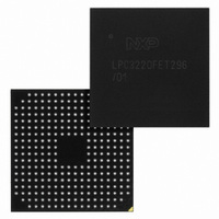
LPC3220FET296/01,5 NXP Semiconductors, LPC3220FET296/01,5 Datasheet - Page 12

LPC3220FET296/01,5
Manufacturer Part Number
LPC3220FET296/01,5
Description
IC ARM9 MCU 128K 296-TFBGA
Manufacturer
NXP Semiconductors
Series
LPC32x0r
Specifications of LPC3220FET296/01,5
Package / Case
296-TFBGA
Core Processor
ARM9
Core Size
16/32-Bit
Speed
266MHz
Connectivity
EBI/EMI, I²C, IrDA, Microwire, SPI, SSI, SSP, UART/USART, USB OTG
Peripherals
DMA, I²S, Motor Control PWM, PWM, WDT
Number Of I /o
51
Program Memory Type
ROMless
Ram Size
128K x 8
Voltage - Supply (vcc/vdd)
0.9 V ~ 3.6 V
Data Converters
A/D 3x10b
Oscillator Type
Internal
Operating Temperature
-40°C ~ 85°C
Processor Series
LPC32
Core
ARM926EJ-S
Data Bus Width
32 bit
Data Ram Size
128 KB
Interface Type
EMC
Maximum Clock Frequency
266 MHz
Number Of Timers
6
Operating Supply Voltage
1.31 V to 1.39 V
Maximum Operating Temperature
+ 85 C
Mounting Style
SMD/SMT
3rd Party Development Tools
MDK-ARM, RL-ARM, ULINK2
Minimum Operating Temperature
- 40 C
On-chip Adc
10 bit, 3 Channel
Lead Free Status / RoHS Status
Lead free / RoHS Compliant
Eeprom Size
-
Program Memory Size
-
Lead Free Status / Rohs Status
Lead free / RoHS Compliant
Other names
568-4965
935290763551
935290763551
Available stocks
Company
Part Number
Manufacturer
Quantity
Price
Company:
Part Number:
LPC3220FET296/01,5
Manufacturer:
NXP Semiconductors
Quantity:
10 000
NXP Semiconductors
1.
ES_LPC3220
Errata sheet
Available GPIO interrupt pins: GPIO_00 to GPIO_05, GPI_00 to GPI_09, GPI_19, GPI_28, and all port 0 and port 1 pins.
3.7 MCPWM.1: Input pins (MCI0-2) on the Motor Control PWM peripheral
are not functional
Introduction:
On the LPC3220, the Motor Control PWM (MCPWM) peripheral is optimized for
three-phase AC and DC motor control applications and can also be used in applications
which require timing, counting, capture, and comparison. The MCPWM contains three
input pins (MCI0-2) for PWM channels 0, 1, and 2. The inputs can be used as feedbacks
for controlling brushless DC motors with Hall sensors, and also can be used to trigger a
Timer/Counter’s (TC) capture or increment a channel’s TC when MCPWM is configured
as a timer/counter.
Note: MCI0-2 pins are also called MCFB0-2 (refer to LPC32x0 User manual for more
details).
Problem:
The input pins (MCI0-2) are not functional.
Work-around:
The GPIO interrupts
LPC3220, the GPIO interrupts can only be set to either trigger on the rising edge or on the
falling edge. Therefore, in order to detect all six states of the connected hall sensor
through an interrupt, the state of the pin needs to be determined and switch to rising or
falling edge interrupt accordingly.
All information provided in this document is subject to legal disclaimers.
1
need to be used instead of the MCPWM MCI0-2 pins. On the
Rev. 8 — 1 February 2011
ES_LPC3220
Errata sheet LPC3220
© NXP B.V. 2011. All rights reserved.
12 of 16


