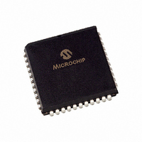
PIC17C44-25/L Microchip Technology, PIC17C44-25/L Datasheet - Page 226

PIC17C44-25/L
Manufacturer Part Number
PIC17C44-25/L
Description
IC MCU OTP 8KX16 PWM 44PLCC
Manufacturer
Microchip Technology
Series
PIC® 17Cr
Datasheets
1.PIC16F616T-ISL.pdf
(8 pages)
2.PIC17C42A-16P.pdf
(241 pages)
3.PIC17C44-16L.pdf
(4 pages)
Specifications of PIC17C44-25/L
Core Size
8-Bit
Program Memory Size
16KB (8K x 16)
Core Processor
PIC
Speed
25MHz
Connectivity
UART/USART
Peripherals
POR, PWM, WDT
Number Of I /o
33
Program Memory Type
OTP
Ram Size
454 x 8
Voltage - Supply (vcc/vdd)
4.5 V ~ 6 V
Oscillator Type
External
Operating Temperature
0°C ~ 70°C
Package / Case
44-PLCC
Controller Family/series
PIC17
No. Of I/o's
33
Ram Memory Size
454Byte
Cpu Speed
25MHz
No. Of Timers
4
No. Of Pwm Channels
2
Embedded Interface Type
USART
Rohs Compliant
Yes
Processor Series
PIC17C
Core
PIC
Data Bus Width
8 bit
Data Ram Size
454 B
Interface Type
SCI, USART
Maximum Clock Frequency
25 MHz
Number Of Programmable I/os
33
Number Of Timers
4
Maximum Operating Temperature
+ 70 C
Mounting Style
SMD/SMT
Development Tools By Supplier
ICE2000
Minimum Operating Temperature
0 C
Lead Free Status / RoHS Status
Lead free / RoHS Compliant
For Use With
AC164317 - MODULE SKT MPLAB PM3 44PLCCDVA17XL441 - DEVICE ADAPTER FOR PIC17C42A309-1007 - ADAPTER 44-PLCC ZIF TO 40-DIPAC174002 - MODULE SKT PROMATEII 44PLCC
Eeprom Size
-
Data Converters
-
Lead Free Status / Rohs Status
Details
Available stocks
Company
Part Number
Manufacturer
Quantity
Price
Company:
Part Number:
PIC17C44-25/L
Manufacturer:
Microchip Technology
Quantity:
10 000
PIC17C4X
Delay From External Clock Edge ....................................... 68
Development Support ...................................................... 143
Development Tools .......................................................... 143
Device Drawings
DIGIT BORROW .................................................................. 9
Digit Carry (DC) .................................................................... 9
Duty Cycle .......................................................................... 75
E
Electrical Characteristics
EPROM Memory Access Time Order Suffix ...................... 31
Extended Microcontroller ................................................... 29
Extended Microcontroller Mode ......................................... 31
External Memory Interface ................................................. 31
External Program Memory Waveforms .............................. 31
F
Family of Devices ................................................................. 6
FERR ........................................................................... 84, 91
FOSC0 ............................................................................... 99
DS30412C-page 226
44-Lead Plastic Surface Mount (MQFP
10x10 mm Body 1.6/0.15 mm Lead Form) .............. 209
PIC17C42
PIC17C43/44
PIC14000 .................................................................. 213
PIC16C5X ................................................................ 214
PIC16CXXX .............................................................. 215
PIC16C6X ................................................................ 216
PIC16C7X ................................................................ 217
PIC16C8X ................................................................ 218
PIC16C9XX............................................................... 219
PIC17CXX ................................................................ 220
Absolute Maximum Ratings ............................. 147
Capture Timing ................................................ 159
CLKOUT and I/O Timing .................................. 156
DC Characteristics ........................................... 149
External Clock Timing ...................................... 155
Memory Interface Read Timing ........................ 162
Memory Interface Write Timing ........................ 161
PWM Timing .................................................... 159
RESET, Watchdog Timer, Oscillator Start-up
Timer and Power-up Timer .............................. 157
Timer0 Clock Timings ...................................... 158
Timer1, Timer2 and Timer3 Clock Timing ........ 158
USART Module, Synchronous Receive ........... 160
USART Module, Synchronous Transmission ... 160
Absolute Maximum Ratings ............................. 175
Capture Timing ................................................ 188
CLKOUT and I/O Timing .................................. 185
DC Characteristics ........................................... 177
External Clock Timing ...................................... 184
Memory Interface Read Timing ........................ 191
Memory Interface Write Timing ........................ 190
Parameter Measurement Information .............. 183
RESET, Watchdog Timer, Oscillator Start-up
Timer and Power-up Timer Timing .................. 186
Timer0 Clock Timing ........................................ 187
Timer1, Timer2 and Timer3 Clock Timing ........ 187
Timing Parameter Symbology .......................... 182
USART Module Synchronous Receive
Timing .............................................................. 189
USART Module Synchronous Transmission
Timing .............................................................. 189
FOSC1 ............................................................................... 99
FS0 .................................................................................... 36
FS1 .................................................................................... 36
FS2 .................................................................................... 36
FS3 .................................................................................... 36
FSR0 ............................................................................ 34, 40
FSR1 ............................................................................ 34, 40
Fuzzy Logic Dev. System ( fuzzy TECH -MP) .......... 143, 145
G
General Format for Instructions ....................................... 108
General Purpose RAM ....................................................... 29
General Purpose RAM Bank ............................................. 42
General Purpose Register (GPR) ...................................... 32
GLINTD .......................................................... 25, 37, 78, 105
GOTO .............................................................................. 122
GPR (General Purpose Register) ...................................... 32
Graphs
H
Hardware Multiplier ............................................................ 49
I
I/O Ports
INCF ................................................................................ 123
INCFSNZ ......................................................................... 124
INCFSZ ............................................................................ 123
INDF0 .......................................................................... 34, 40
INDF1 .......................................................................... 34, 40
I
I
I
I
Maximum I
(External Clock 125 C to -40 C) ...................... 167, 197
Maximum I
Maximum I
RC Oscillator Frequency vs.
V
RC Oscillator Frequency vs.
V
RC Oscillator Frequency vs.
V
Transconductance of LF Oscillator vs.V
Transconductance of XT Oscillator vs. V
Typical I
(External Clock 25 C) ...................................... 167, 197
Typical I
Typical I
Typical RC Oscillator vs. Temperature ............ 163, 193
V
V
V
(In XT, HS, and LP Modes) vs. V
V
(In RC Mode) vs. V
WDT Timer Time-Out Period vs. V
Bi-directional .............................................................. 64
I/O Ports .................................................................... 53
Programming Considerations .................................... 64
Read-Modify-Write Instructions ................................. 64
Successive Operations .............................................. 64
OH
OH
OL
OL
DD
DD
DD
TH
DD
TH
TH
vs. V
vs. V
, V
vs. V
vs. V
(Input Threshold Voltage) of I/O Pins vs.
(Input Threshold Voltage) of OSC1 Input
(Cext = 100 pF) ........................................ 164, 194
(Cext = 22 pF) .......................................... 164, 194
(Cext = 300 pF) ........................................ 165, 195
.................................................................. 172, 202
IL
DD
PD
PD
OL
OL
of MCLR, T0CKI and OSC1
OH
OH
DD
PD
PD
, V
, V
vs. V
vs. V
, V
, V
vs. Frequency
DD
DD
vs. V
vs. V
vs. Frequency
DD
DD
DD
DD
= 3V ...................................... 171, 201
= 5V ...................................... 172, 202
= 3V ..................................... 170, 200
= 5V ..................................... 171, 201
DD
DD
DD
Watchdog Disabled 25 C . 168, 198
Watchdog Enabled 25 C .. 169, 199
Watchdog Disabled ...... 168, 198
Watchdog Enabled ...... 169, 199
...................................... 173, 203
1996 Microchip Technology Inc.
DD
DD
................ 173, 203
.............. 170, 200
DD
DD
...... 166, 196
.... 166, 196


