AT91SAM7S32B-MU Atmel, AT91SAM7S32B-MU Datasheet - Page 629
AT91SAM7S32B-MU
Manufacturer Part Number
AT91SAM7S32B-MU
Description
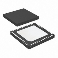
IC MCU ARM7 32KB FLASH 48-VQFN
Manufacturer
Atmel
Series
AT91SAMr
Datasheet
1.AT91SAM7S16-MU.pdf
(779 pages)
Specifications of AT91SAM7S32B-MU
Core Processor
ARM7
Core Size
16/32-Bit
Speed
55MHz
Connectivity
I²C, SPI, SSC, UART/USART
Peripherals
Brown-out Detect/Reset, DMA, POR, PWM, WDT
Number Of I /o
21
Program Memory Size
32KB (32K x 8)
Program Memory Type
FLASH
Ram Size
8K x 8
Voltage - Supply (vcc/vdd)
1.65 V ~ 1.95 V
Data Converters
A/D 8x10b
Oscillator Type
Internal
Operating Temperature
-40°C ~ 85°C
Package / Case
48-VQFN Exposed Pad, 48-HVQFN, 48-SQFN, 48-DHVQFN
For Use With
AT91SAM-ICE - EMULATOR FOR AT91 ARM7/ARM9AT91SAM7S-EK - KIT EVAL FOR ARM AT91SAM7S
Lead Free Status / RoHS Status
Lead free / RoHS Compliant
Eeprom Size
-
Available stocks
Company
Part Number
Manufacturer
Quantity
Price


40.7.8
40.7.8.1
40.7.8.2
40.7.8.3
40.7.8.4
40.7.8.5
6175K–ATARM–30-Aug-10
Serial Peripheral Interface (SPI)
SPI: Bad tx_ready Behavior when CSAAT = 1 and SCBR = 1
SPI: LASTXFER (Last Transfer) Behavior
SPI: Chip Select and Fixed Mode
SPI: Baudrate Set to 1
SPI: SPCK Behavior in Master Mode
If the SPI is programmed with CSAAT = 1, SCBR(baudrate) = 1 and two transfers are performed
consecutively on the same slave with an IDLE state between them, the tx_ready signal does not
rise after the second data has been transferred in the shifter. This can imply for example, that
the second data is sent twice.
Do not use the combination CSAAT = 1 and SCBR = 1.
In FIXED Mode, with CSAAT bit set, and in “PDC mode” the Chip Select can rise depending on
the data written in the SPI_TDR when the TX_EMPTY flag is set. If for example, the PDC writes
a “1” in the bit 24 (LASTXFER bit) of the SPI_TDR, the chip select will rise as soon as the
TXEMPTY flag is set.
Use the CS in PIO mode when PDC mode is required and CS has to be maintained between
transfers.
SPCK pin can toggle out before the first transfer in Master Mode.
Problem Fix/Workaround
In Master Mode, MSTR bit must be set (in SPI_MR register) before configuring SPI_CSRx
registers.
In fixed Mode, if a transfer is performed through a PDC on a Chip select different from the Chip
select 0, the output spi_size sampled by the PDC will depend on the field, BITS (Bits per Trans-
fer) of SPI_CSR0 register, whatever the selected Chip select is. For example, if SPI_CSR0 is
configured for a 10-bit transfer whereas SPI_CSR1 is configured for an 8-bit transfer, when a
transfer is performed in Fixed mode through the PDC, on Chip select 1, the transfer will be con-
sidered as a HalfWord transfer.
If a PDC transfer has to be performed in 8 bits, on a Chip select y (y as different from 0), the
BITS field of the SPI_CSR0 must be configured in 8 bits, in the same way as the BITS field of
the CSRy Register.
When Baudrate is set at 1 (i.e. when serial clock frequency equals the system clock frequency)
and when the BITS field of the SPI_CSR register (number of bits to be transmitted) equals an
ODD value (in this case 9,11,13 or 15), an additional pulse will be generated on output SPCK.
Everything is OK if the BITS field equals 8,10,12,14 or 16 and Baudrate = 1.
None.
Problem Fix/Workaround
Problem Fix/Workaround
Problem Fix/Workaround
Problem Fix/Workaround
AT91SAM7S Series Preliminary
629
Related parts for AT91SAM7S32B-MU
Image
Part Number
Description
Manufacturer
Datasheet
Request
R

Part Number:
Description:
KIT EVAL FOR ARM AT91SAM7S
Manufacturer:
Atmel
Datasheet:

Part Number:
Description:
MCU, MPU & DSP Development Tools KICKSTART KIT ATMEL AT91SAM7S
Manufacturer:
IAR Systems

Part Number:
Description:
DEV KIT FOR AVR/AVR32
Manufacturer:
Atmel
Datasheet:

Part Number:
Description:
INTERVAL AND WIPE/WASH WIPER CONTROL IC WITH DELAY
Manufacturer:
ATMEL Corporation
Datasheet:
Part Number:
Description:
Low-Voltage Voice-Switched IC for Hands-Free Operation
Manufacturer:
ATMEL Corporation
Datasheet:
Part Number:
Description:
MONOLITHIC INTEGRATED FEATUREPHONE CIRCUIT
Manufacturer:
ATMEL Corporation
Datasheet:
Part Number:
Description:
AM-FM Receiver IC U4255BM-M
Manufacturer:
ATMEL Corporation
Datasheet:
Part Number:
Description:
Monolithic Integrated Feature Phone Circuit
Manufacturer:
ATMEL Corporation
Datasheet:
Part Number:
Description:
Multistandard Video-IF and Quasi Parallel Sound Processing
Manufacturer:
ATMEL Corporation
Datasheet:
Part Number:
Description:
High-performance EE PLD
Manufacturer:
ATMEL Corporation
Datasheet:
Part Number:
Description:
8-bit Flash Microcontroller
Manufacturer:
ATMEL Corporation
Datasheet:
Part Number:
Description:
2-Wire Serial EEPROM
Manufacturer:
ATMEL Corporation
Datasheet: