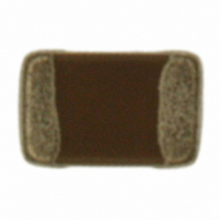
ECJ-2F60J226M Panasonic - ECG, ECJ-2F60J226M Datasheet - Page 7

ECJ-2F60J226M
Manufacturer Part Number
ECJ-2F60J226M
Description
CAP CERAMIC 22UF 6.3V 0805 X6S
Manufacturer
Panasonic - ECG
Series
ECJr
Datasheets
1.ECJ-RVB1H332M.pdf
(6 pages)
2.ECJ-RVB1H332M.pdf
(2 pages)
3.ECJ-RVB1H332M.pdf
(1 pages)
4.ECJ-RVB1H332M.pdf
(3 pages)
5.ECJ-2F60J226M.pdf
(24 pages)
Specifications of ECJ-2F60J226M
Capacitance
22µF
Voltage - Rated
6.3V
Tolerance
±20%
Temperature Coefficient
X6S
Mounting Type
Surface Mount, MLCC
Operating Temperature
-55°C ~ 105°C
Features
Low ESR
Applications
General Purpose
Package / Case
0805 (2012 Metric)
Size / Dimension
0.079" L x 0.049" W (2.00mm x 1.25mm)
Thickness
1.25mm
Lead Free Status / RoHS Status
Lead free / RoHS Compliant
Ratings
-
Lead Spacing
-
Other names
ECJ2F60J226M
PCC2477TR
PCC2477TR
CLASSIFICATION
SUBJECT
Note ;
No
13
14
15
Temperature
cycle
Moisture
Resistance
Moisture
Resistant
Loading
High Capacitance (P/N : ECJ2F60J226M) Common Specification
Contents
Multilayer Ceramic Chip Capacitors (EIA 0805)
Appear-
ance
Capaci-
tance
tan δ
I.R.
With-
stand
voltage
Appear-
ance
Capaci-
tance
tan δ
I.R.
Appear-
ance
Capaci-
tance
tan δ
I.R.
There shall be no cracks and other
mechanical damage.
Shall meet the specified initial value.
Shall meet the specified initial value.
There shall be no dielectric break-
down or damage.
There shall be no cracks and other
mechanical damage.
0.25 max.
10/C MΩ min.
(C : Nominal Cap. in µF)
There shall be no cracks and other
Mechanical damage.
0.25 max.
5/C MΩ min.
(C : Nominal Cap. in µF)
Temp.
Temp.
Temp.
Char.
Char.
Char.
X6S
X6S
X6S
SPECIFICATION
Change from the value
Within +/- 7.5 %
Change from the value
Within +/- 20 %
Change from the value
Within +/- 20 %
before test.
before test.
before test.
Performance
(continue)
Table 2
Solder the specimen to the testing jig shown
in Fig. 2. Condition the specimen to each
temperature from step 1 to 4 in this order for
the period shown in the table below. Regard-
ing this conditioning as one cycle, perform
5 cycles continuously.
For the class2 capacitors, perform the heat
treatment in par. 5-1-1.
Before the measurement after test, the
specimen shall be left to stand at room
For the class2 capacitors, perform the heat
treatment in par. 5-1-1.
Solder the specimen to the testing jig shown
in Fig. 2.
Before the measurement after test, the spe-
cimen shall be left to stand at room tempera-
ture for the following period :
For the class2 capacitors, perform the heat
treatment in par. 5-1-2.
Solder the specimen to the testing jig shown
in Fig. 2.
Before the measurement after test, the spe-
cimen shall be left to stand at room tempera-
ture for the following period :
temperature for the following period :
Step
Test temperature : 40+/-2 °C
Relative humidity : 90 to 95 %
Test period : 500+24/0 h
Test temperature : 40+/-2 °C
Relative humidity : 90 to 95 %
Applied voltage : Rated voltage
Charge/discharge current : within 50 mA.
Test period : 500+24/0 h
1
2
3
4
48+/-4 h
48+/-4 h
48+/-4 h
Maximum operation
Minimum operation
Room temperature
Room temperature
temperature +/- 3
temperature +/-5
Temperature
Test Method
(°C)
(DC Voltage)
No.
PAGE
DATE
151S-ECJ-KGS39E
Aug 28, 2008
5 of 7
3 max.
3 max.
Period
30+/-3
30+/-3
(min.)


