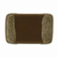
ECJ-2F60J226M Panasonic - ECG, ECJ-2F60J226M Datasheet - Page 11

ECJ-2F60J226M
Manufacturer Part Number
ECJ-2F60J226M
Description
CAP CERAMIC 22UF 6.3V 0805 X6S
Manufacturer
Panasonic - ECG
Series
ECJr
Datasheets
1.ECJ-RVB1H332M.pdf
(6 pages)
2.ECJ-RVB1H332M.pdf
(2 pages)
3.ECJ-RVB1H332M.pdf
(1 pages)
4.ECJ-RVB1H332M.pdf
(3 pages)
5.ECJ-2F60J226M.pdf
(24 pages)
Specifications of ECJ-2F60J226M
Capacitance
22µF
Voltage - Rated
6.3V
Tolerance
±20%
Temperature Coefficient
X6S
Mounting Type
Surface Mount, MLCC
Operating Temperature
-55°C ~ 105°C
Features
Low ESR
Applications
General Purpose
Package / Case
0805 (2012 Metric)
Size / Dimension
0.079" L x 0.049" W (2.00mm x 1.25mm)
Thickness
1.25mm
Lead Free Status / RoHS Status
Lead free / RoHS Compliant
Ratings
-
Lead Spacing
-
Other names
ECJ2F60J226M
PCC2477TR
PCC2477TR
CLASSIFICATION
SUBJECT
2- 2.Design of Printed Circuit Board
Note ;
2-1-7. Capacitance aging
2-1-8. Piezoelectricity
2-2-1. Selection of Printed Circuit Board
Dielectrics used for the Capacitors (Class 2) may cause the following Piezoelectricity (or Electrostriction).
When the Capacitors are mounted and soldered on an Aluminum Substrate, the substrate has influences on
Capacitor’s reliabilities against “Temperature Cycles” and “Heat shock” because of difference in thermal
expansion coefficient between them.
It shall be carefully confirmed that the actual board applied does not deteriorate the characteristics of the
Capacitors.
The ceramic dielectrics of the Capacitors (Class 2) have capacitance aging. Accordingly, when the Capacitors
are used for the circuits, which require a narrow capacitance allowable range, such as time constant circuits,
pay due consideration to capacitance aging for use.
(1) If the signal of a specific frequency is applied to the Capacitors, electric and acoustic noise may be
(2) Vibration or impact applied to the Capacitors may cause noise because mechanical force is converted to
(3) Even if a whining sound is generated, there is no problem in product performance and reliability, however,
generated by resonating the characteristic frequency which is determined by the dimensions of the
Capacitor.
As a measure to prevent this phenomenon, changing the size of the Capacitor is effective to change its
resonance frequency.
Also there is another measure changing the materials of the Capacitors to the Low-loss type, which has no
(or less) piezoelectricity, or to Class1.
which has no (or less) piezoelectricity, or to Class1 is also available.
electrical signals (Especially, application to around the amplifier unit) .
As a measure to prevent this phenomenon, changing the materials of the Capacitor to the Low-loss type,
which has no (or less) piezoelectricity, or to Class1 is also available.
check the worrisome phenomenon which may generate noise in your equipment.
As a measure to prevent this phenomenon, changing to the Capacitor different in characteristics, size and
shape as shown in the (1), (2) above is effective.
As the other measures, changing the mounting direction of the Capacitors to bring under control the
resonance with equipment bodies such as printed circuit board, or the Capacitors are fixed with equipment
bodies such as printed circuit board by adhesive may be effective.
Capacitance change vs. DC voltage
Under Ordinary Temperature
Common Specification ( Precautions for Use)
Multilayer Ceramic Chip Capacitor
Time (h)
DC voltage (V)
SPECIFICATIONS
Before and After Heat treatment
Heat treatment
Time (h)
No.
PAGE
DATE
151S-ECJ-SS018E
Apr. 1, 2008
2 of 9


