ECJ-2F60J226M Panasonic - ECG, ECJ-2F60J226M Datasheet - Page 13
ECJ-2F60J226M
Manufacturer Part Number
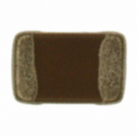
ECJ-2F60J226M
Description
CAP CERAMIC 22UF 6.3V 0805 X6S
Manufacturer
Panasonic - ECG
Series
ECJr
Datasheets
1.ECJ-RVB1H332M.pdf
(6 pages)
2.ECJ-RVB1H332M.pdf
(2 pages)
3.ECJ-RVB1H332M.pdf
(1 pages)
4.ECJ-RVB1H332M.pdf
(3 pages)
5.ECJ-2F60J226M.pdf
(24 pages)
Specifications of ECJ-2F60J226M
Capacitance
22µF
Voltage - Rated
6.3V
Tolerance
±20%
Temperature Coefficient
X6S
Mounting Type
Surface Mount, MLCC
Operating Temperature
-55°C ~ 105°C
Features
Low ESR
Applications
General Purpose
Package / Case
0805 (2012 Metric)
Size / Dimension
0.079" L x 0.049" W (2.00mm x 1.25mm)
Thickness
1.25mm
Lead Free Status / RoHS Status
Lead free / RoHS Compliant
Ratings
-
Lead Spacing
-
Other names
ECJ2F60J226M
PCC2477TR
PCC2477TR


CLASSIFICATION
SUBJECT
Note ;
2-2-3. Utilization of Solder Resist
2-2-4. Component Layout
Mixed mounting
with a component with
lead wires
Arrangement
near chassis
Retrofitting of
Component with lead
wires
Lateral arrangement
Warp of
Circuit board
The application of solder resist is effective in preventing solder bridges and controlling the amount of solder on
PC boards.
The Capacitors / components shall be placed on the PC board such that both electrodes are subjected to
uniform stresses, or to position the component electrodes at right angles to the grid glove or bending line. This
should be done to avoid cracking the Capacitors from bending the PC board after or during placing/mounting on
the PC board.
See the table below.
(1) To minimize mechanical stress caused by warp or bending of a PC board, please follow the recommended
(2) The following drawing is for your reference since
(3) The magnitude of mechanical stress applied to
Capacitor layout below.
mechanical stress near the dividing/breaking
position of a PC board varies depending on the
mounting position of the Capacitors.
the Capacitors when the circuit board is divided is
in the order of push back < slit < V-groove <
perforation.
Also take into account the layout of the
Capacitors and the dividing/breaking method.
(1)Solder resist shall be utilized to equalize the amounts of solder on both sides.
(2)Solder resist shall be used to divide the pattern for the following cases;
・Components are arranged closely.
・The Capacitor is mounted near a component with lead wires.
・The Capacitor is placed near a chassis.
Common Specification ( Precautions for Use)
Multilayer Ceramic Chip Capacitor
Prohibited layout
Soldering iron
Land
Prohibited Applications and Recommended Applications
Chassis
SPECIFICATIONS
Solder (ground solder)
Prohibited applications
The lead wire of
a component with
Portion to be
Lead wire of
excessively
Sectional view
Sectional view
Sectional view
Retrofitted
component
lead wires
soldered
Perforation
Recommended layout
Improved applications by pattern division
Magnitude of stress A>B=C>D>E
Solder resist
Solder resist
Solder resist
A
E
Lay out the Capacitor
Slit
sideways against the
C
stressing direction
No.
PAGE
DATE
151S-ECJ-SS018E
Sectional view
Solder resist
D
Sectional view
Sectional view
Apr. 1, 2008
B
4 of 9
Related parts for ECJ-2F60J226M
Image
Part Number
Description
Manufacturer
Datasheet
Request
R

Part Number:
Description:
CAP ARRAY 22PF 50V NP0 0504
Manufacturer:
Panasonic - ECG
Datasheet:
Part Number:
Description:
CAP ARRAY 10PF 50V NP0 0504
Manufacturer:
Panasonic - ECG
Datasheet:
Part Number:
Description:
CAP ARRAY 100PF 50V NP0 0504
Manufacturer:
Panasonic - ECG
Datasheet:
Part Number:
Description:
CAP ARRAY 47PF 50V NP0 0504
Manufacturer:
Panasonic - ECG
Datasheet:
Part Number:
Description:
CAP ARRAY 2.2UF 6.3V X5R 0504
Manufacturer:
Panasonic - ECG
Datasheet:
Part Number:
Description:
CAP ARRAY .1UF 10V X5R 0504
Manufacturer:
Panasonic - ECG
Datasheet:
Part Number:
Description:
CAP ARRAY 1UF 6.3V X5R 0504
Manufacturer:
Panasonic - ECG
Datasheet:
Part Number:
Description:
CAP ARRAY 1UF 6.3V X5R 0504
Manufacturer:
Panasonic - ECG
Datasheet:
Part Number:
Description:
CAP ARRAY 1UF 10V X5R 0504
Manufacturer:
Panasonic - ECG
Datasheet:
Part Number:
Description:
CAP ARRAY 1UF 10V X5R 0504
Manufacturer:
Panasonic - ECG
Datasheet:


Part Number:
Description:
MICROPHONE OMNI 6X2.2MM W/CAP
Manufacturer:
Panasonic - ECG
Datasheet:

Part Number:
Description:
CAP .01UF 100V PEN FILM 1210 5%
Manufacturer:
Panasonic - ECG
Datasheet:

Part Number:
Description:
FILTER LINE 23.3MH 2A
Manufacturer:
Panasonic - ECG
Datasheet:

Part Number:
Description:
SAW FILTER PCS 1960 MHZ 50/150
Manufacturer:
Panasonic - ECG
Datasheet: