AS5030 AB austriamicrosystems, AS5030 AB Datasheet - Page 32
AS5030 AB
Manufacturer Part Number
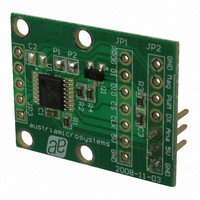
AS5030 AB
Description
BOARD ADAPTER AS5030
Manufacturer
austriamicrosystems
Specifications of AS5030 AB
Sensor Type
Magnetic, Rotary Position
Sensing Range
360°
Interface
Serial
Voltage - Supply
5V
Embedded
No
Utilized Ic / Part
AS5030
Lead Free Status / RoHS Status
Lead free by exemption / RoHS compliant by exemption
Sensitivity
-


AS5030
Datasheet - A p p l i c a t i o n I n f o r m a t i o n
Hys = 1.
The differentiator between Low Power Mode and Ultra Low Power Mode is the current consumption and the wake-up time to switch back to
active operation.
In both Reduced Power Modes, the AS5030 is inactive. The last state, e.g. the angle, AGC value, etc. is frozen and the chip starts from this
frozen state when it resumes active operation. This method provides much faster start-up than a “cold start” from zero. If the AS5030 is cycled
between active and reduced current mode, a substantial reduction of the average supply current can be achieved. The minimum dwelling time in
active mode is the wake-up time. The actual active time depends on how much the magnet has moved while the AS5030 was in reduced power
mode. The angle data is valid, when the status bit LOCK has been set. Once a valid angle has been measured, the AS5030 can be put back to
reduced power mode. The average power consumption can be calculated as:
Where:
I
I
I
t
t
Example: Ultra Low Power Mode; sampling period = one measurement every 10ms.
System constants = I
See
Reducing Power Supply Peak Currents.
An optional RC-filter (R1/C1) may be added to avoid peak currents in the power supply line when the AS5030 is toggled between active and
reduced power mode. R1 must be chosen such that it can maintain a VDD voltage of 4.5V ~ 5.5V under all conditions, especially during long
active periods when the charge on C1 has expired. C1 should be chosen such that it can support peak currents during the active operation
period. For long active periods, C1 should be large and R1 should be small.
www.austriamicrosystems.com/AS5030
I
avg
active
power_down
on
off
Ultra Low Power Mode
avg
:time period during which the chip is operated in active mode
: time period during which the chip is in reduced power mode
Low Power Mode
Figure 27
average current consumption
Active operation
: current consumption in active mode
1. Wait for CPU interrupt or delay for next angle read (typ. <3ms in LP mode, typ>3ms in ULP mode)
2. Wake up (PSM = 0)
3. Wait 0.01ms (Low Power Mode)
4. Check if Lock = 1 then read angle
5. Enable Low Power Mode or Ultra Low Power Mode (PSM=1)
6. Return to 1
=
(No hysteresis)
Mode
I
:current consumption in reduced power mode
active
for an overview table of the average current consumption in the various reduced power modes.
∗
t
active
on
t
+
on
= 14mA, I
Current Consumption
I
+
power
t
off
power_down
_
1.4 mA
14 mA
30 µA
(typ.)
down
I
avg
∗
=
t
= 30µA, ton(min) = 500µs (startup from Ultra Low Power Mode):
off
14
mA
sampling interval = t
Wake-up Time to Active
3.8 ms (with locked AGC)
1.0 ms (without AGC)
∗
500
500
Operation
0.15 ms
0.5 ms
μ
μ
s
s
Revision 2.1
+
+
9
30
5 ,
μ
ms
on
A
*
+ t
9
off
5 ,
ms
=
729
μ
A
32 - 44
(EQ 6)
(EQ 7)
Related parts for AS5030 AB
Image
Part Number
Description
Manufacturer
Datasheet
Request
R

Part Number:
Description:
IC ENCODER ROTARY 8-BIT 16-TSSOP
Manufacturer:
austriamicrosystems
Datasheet:

Part Number:
Description:
BOARD DEMO AS5030
Manufacturer:
austriamicrosystems
Datasheet:
Part Number:
Description:
IC ENCODER ROTARY 8-BIT 16-TSSOP
Manufacturer:
austriamicrosystems
Datasheet:
Part Number:
Description:
8-bit High-speed Absolute Magnetic Rotary Encoder
Manufacturer:
austriamicrosystems
Datasheet:
Part Number:
Description:
IC SWITCH QUAD SPST 14-TSSOP
Manufacturer:
austriamicrosystems
Datasheet:
Part Number:
Description:
IC SWITCH QUAD SPST 14-TSSOP
Manufacturer:
austriamicrosystems
Datasheet:
Part Number:
Description:
IC AMP AUDIO MONO 1.8W 10-MSOP
Manufacturer:
austriamicrosystems
Datasheet:
Part Number:
Description:
IC AMP AUDIO MONO 1.8W 10-MSOP
Manufacturer:
austriamicrosystems
Datasheet:
Part Number:
Description:
IC AMP AUDIO MONO 1.8W 10-MSOP
Manufacturer:
austriamicrosystems
Datasheet:
Part Number:
Description:
IC AMP AUD 1.8W 3DB GAIN 10-MSOP
Manufacturer:
austriamicrosystems
Datasheet:
Part Number:
Description:
IC DRIVER LED 8-DIGIT 24-SOIC
Manufacturer:
austriamicrosystems
Datasheet:
Part Number:
Description:
IC DRIVER LED 8-DIGIT 24-SOIC
Manufacturer:
austriamicrosystems
Datasheet:
Part Number:
Description:
IC, LINE/SPEAKER PHONE CIRCUIT, SOIC-28
Manufacturer:
austriamicrosystems
Datasheet:
Part Number:
Description:
IC MULTI-STANDARD CMOS TELEPHONE SOIC-28
Manufacturer:
austriamicrosystems
Datasheet:
Part Number:
Description:
IC MULTI-STANDARD CMOS TELEPHONE SOIC-28
Manufacturer:
austriamicrosystems
Datasheet: