AS5030 AB austriamicrosystems, AS5030 AB Datasheet - Page 24
AS5030 AB
Manufacturer Part Number
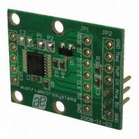
AS5030 AB
Description
BOARD ADAPTER AS5030
Manufacturer
austriamicrosystems
Specifications of AS5030 AB
Sensor Type
Magnetic, Rotary Position
Sensing Range
360°
Interface
Serial
Voltage - Supply
5V
Embedded
No
Utilized Ic / Part
AS5030
Lead Free Status / RoHS Status
Lead free by exemption / RoHS compliant by exemption
Sensitivity
-


AS5030
Datasheet - A p p l i c a t i o n I n f o r m a t i o n
8.2.2 16-bit Write Command
These settings are temporary; they cannot be programmed permanently. The settings will be lost when the power supply is removed.
EN PROG command must be sent with a fixed 16-bit code (8CAE
ULP/LPn selects the Ultra Low Power Mode, when bit PSM is set: 0 = Low Power Mode, 1 = Ultra Low Power Mode
PSM enables power saving modes: 0 = normal operation, 1 = reduced power mode selected by bit ULP/LPn
HYS disables the hysteresis of the digital serial and PWM outputs:
DIS AGC disables the automatic gain control. The AGC will be frozen to a gain setting written in bits AGC 5:0 (D6:D1), bit FA must be set.
rst General Reset: 0 = normal operation, 1 = perform general reset (required after return from reduced power modes)
FA Freeze AGC; 0 = normal operation, 1= freeze AGC with the values stored in bits AGC 5:0. The PWM output will be invalid when bit FA is set.
8.2.3 18-bit OTP Read Commands
Note: To prohibit unintentional access to the OTP register, OTP PROG/write access is only enabled after the EN PROG command has been
EN PROG has not to be sent before a READ OTP.
During the 18bit OTP read/write transfer, each bit needs 4 clock pulses to be validated.
READ OTP reads the contents of the OTP register in digital form. The reserved area may contain any value
ANALOG OTP RD reads the contents of the OTP register as an analog voltage at pin PROG
sens reads the sensitivity setting of the Hall elements: 00 = low sensitivity, 11 = high sensitivity
zero position reads the programmed zero position; the actual angle of the magnet which is displayed as 000
www.austriamicrosystems.com/AS5030
READ OTP 01111
Command
Command
EN PROG
DIS HYST
SET PWR
DIS AGC
ANALOG
OTP RD
MODE
0 (default) = 1-bit hysteresis, 1 = no hysteresis
sent. OTP access is locked again by sending a RD ANGLE or SET PWR MODE command.
01001
10000
10001
10101
10011
Bin
Bin
Hex D17
0F
09
Hex
10
13
15
11
ULP/
HYS
D15
LPn
1
0
D16
PSM
D14
reserved for factory settings
reserved for factory settings
0
0
D15 D14 D13 D12 D11 D10 D9 D8
D13 D12 D11 D10
0
0
0
0
1
0
H
) to enable subsequent OTP access.
Revision 2.1
rst
1
D9
0
0
D8
0
0
sens
sens
1:0
1:0
D7
0
1
0
0
D7
D6
0
D6
D5
1
D5
D4
AGC 5:0
0
zero position
zero position
D4
7:0
7:0
D3
1
D3
D2
1
D2
D1
1
D1
24 - 44
D0
FA
D0
0
Related parts for AS5030 AB
Image
Part Number
Description
Manufacturer
Datasheet
Request
R

Part Number:
Description:
IC ENCODER ROTARY 8-BIT 16-TSSOP
Manufacturer:
austriamicrosystems
Datasheet:

Part Number:
Description:
BOARD DEMO AS5030
Manufacturer:
austriamicrosystems
Datasheet:
Part Number:
Description:
IC ENCODER ROTARY 8-BIT 16-TSSOP
Manufacturer:
austriamicrosystems
Datasheet:
Part Number:
Description:
8-bit High-speed Absolute Magnetic Rotary Encoder
Manufacturer:
austriamicrosystems
Datasheet:
Part Number:
Description:
IC SWITCH QUAD SPST 14-TSSOP
Manufacturer:
austriamicrosystems
Datasheet:
Part Number:
Description:
IC SWITCH QUAD SPST 14-TSSOP
Manufacturer:
austriamicrosystems
Datasheet:
Part Number:
Description:
IC AMP AUDIO MONO 1.8W 10-MSOP
Manufacturer:
austriamicrosystems
Datasheet:
Part Number:
Description:
IC AMP AUDIO MONO 1.8W 10-MSOP
Manufacturer:
austriamicrosystems
Datasheet:
Part Number:
Description:
IC AMP AUDIO MONO 1.8W 10-MSOP
Manufacturer:
austriamicrosystems
Datasheet:
Part Number:
Description:
IC AMP AUD 1.8W 3DB GAIN 10-MSOP
Manufacturer:
austriamicrosystems
Datasheet:
Part Number:
Description:
IC DRIVER LED 8-DIGIT 24-SOIC
Manufacturer:
austriamicrosystems
Datasheet:
Part Number:
Description:
IC DRIVER LED 8-DIGIT 24-SOIC
Manufacturer:
austriamicrosystems
Datasheet:
Part Number:
Description:
IC, LINE/SPEAKER PHONE CIRCUIT, SOIC-28
Manufacturer:
austriamicrosystems
Datasheet:
Part Number:
Description:
IC MULTI-STANDARD CMOS TELEPHONE SOIC-28
Manufacturer:
austriamicrosystems
Datasheet:
Part Number:
Description:
IC MULTI-STANDARD CMOS TELEPHONE SOIC-28
Manufacturer:
austriamicrosystems
Datasheet: