AS5030 AB austriamicrosystems, AS5030 AB Datasheet
AS5030 AB
Specifications of AS5030 AB


Related parts for AS5030 AB


AS5030 AB Summary of contents
Page 1
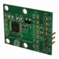
... A Power Down Mode together with fast startup- and measurement cycles allows for very low average power consumption and makes the AS5030 also suitable for battery operated equipment. Figure 1: AS5030 Adapterboard www.austriamicrosystems.com AS5030-AB-2.0 Adapterboard OPERATION MANUAL JP1 connector (Alarm, PWM, analog, power supply) ...
Page 2
... The airgap between the magnet and the AS5030 casing should be maintained in the range 0.5mm~2mm. The magnet holder must not be ferromagnetic. Materials as brass, copper, aluminum, stainless steel are the best choices to make this part. Revision 1.0, 26.February 2009 Bearing www.austriamicrosystems.com Casing Spacer AS5030-AB PCB JP2 connector, 3 pin ...
Page 3
... Configuration input for serial wire mode: - Connect to VSS for 3-wire operation (P2 closed, by default) - High level (P2 open) for 2-wire operation This pin is scanned at power-on-reset and at wakeup from one of the Ultra Low Power Modes DO: digital output DO_T: digital output / tri-state DI: digital input (standard CMOS; no pull-up or pull-down) www.austriamicrosystems.com Page ...
Page 4
... PWM signal (JP2 pin #5) with a period of 581us, 2.26us step and 5V pulse voltage can be connected to the capture/timer input of a microcontroller in order to decode the angle value. Figure 6: PWM duty cycle depending on magnet position www.austriamicrosystems.com Page ...
Page 5
... The MCU GPIO used for the DIO data signal should be bi-directional: the MCU sends a 5 bit command first then receives a 16 bit value on the same line. The DI input of the adapter board must be connected to GND in this mode. The C source code for reading an angle with this hardware configuration is described in Chapter 7. www.austriamicrosystems.com Page ...
Page 6
... Independent of the number of connected devices, the interface to the controller remains the same with only three signals: CSn, CLK and DO. In Daisy Chain mode, the data from the second and subsequent devices is appended to the data of the first device. See AS5030 datasheet chapter 4.21. www.austriamicrosystems.com Page ...
Page 7
... GND TC DX AS5030 Q1 BSS138 GND 100k C1 Solder_Bridge JP2 5V 7 GND MagRNGn 6 PWM Analog 100k GND Solder_Bridge Header 7 OPTIONAL I/O www.austriamicrosystems.com Analog C3 2.2u/10V Closed: SinCos output disabled (default) Open: SinCos output enabled GND Closed: 3 wire mode (Default) Open: 2 wire mode GND Page ...
Page 8
... DIO (push-pull output) // Otherwise send ‘0’ on DIO (push-pull output Last Bit has been written // Set Clock // And DIO output of CPU in input mode // Clear Clock (datasheet timings) www.austriamicrosystems.com // Value of bit 5, then // bit 4, …, bit 0 Page ...
Page 9
... Serial daisy chain mode............................................................................................................................................ 6 6 AS5030 adapterboard hardware ....................................................................................................................................... 7 6.1 AS5030-AB-2.0 schematics...................................................................................................................................... 7 6.2 AS5030-AB-2.0 PCB layout...................................................................................................................................... 7 7 C-Source code, simple AGC & Angle read........................................................................................................................ 8 Table of contents........................................................................................................................................................................ 9 Copyrights ................................................................................................................................................................................ 10 Disclaimer................................................................................................................................................................................. 10 Contact Information .................................................................................................................................................................. 10 Revision 1.0, 26.February 2009 www.austriamicrosystems.com Page ...
Page 10
... No obligation or liability to recipient or any third party shall arise or flow out of austriamicrosystems AG rendering of technical or other services. ...