AS5030 AB austriamicrosystems, AS5030 AB Datasheet - Page 22
AS5030 AB
Manufacturer Part Number
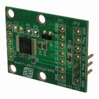
AS5030 AB
Description
BOARD ADAPTER AS5030
Manufacturer
austriamicrosystems
Specifications of AS5030 AB
Sensor Type
Magnetic, Rotary Position
Sensing Range
360°
Interface
Serial
Voltage - Supply
5V
Embedded
No
Utilized Ic / Part
AS5030
Lead Free Status / RoHS Status
Lead free by exemption / RoHS compliant by exemption
Sensitivity
-


AS5030
Datasheet - A p p l i c a t i o n I n f o r m a t i o n
8 Application Information
AS5030 Parameter and Features List.
www.austriamicrosystems.com/AS5030
Absolute output; Serial Interface
Non-valid-range indication
OTP programming mode
Resolution and accuracy
Operating temperature
Digital output current
2-wire readout mode
Magnetic field range
Power down modes
Digital input cells
Maximum speed
Transition noise
Start-up timings
SIN-COS mode
ESD protection
Supply voltage
Supply current
SSI clock rate
PWM output
Parameter
5V ± 10%
Low Power Mode, non-operational: typ. 1.4mA
Ultra Low Power Mode, non-operational: typ. 30µA
Normal operating mode: typ. 14mA.
21-bit Synchronous Serial Interface (SSI): 5 command bits, 2 data valid bits, 6 data bits for magnetic
field strength, 8 data bits for angle.
Configurable for 2-wire (Clock, Data) or 3-wire (Chip Select, Clock, Data) operation
Daisy Chain mode for reading multiple encoders through a 2- or 3-wire interface.
Zero Position Programming (OTP)
≤ 6 MHz data clock rate, 250 ~ 500kHz during programming
DIO and CLK signals. 0.1 ~ 6MHz clock rate. Synchronization through time-out of CLK signal.
Activated and deactivated by software commands.
Low Power Mode: power down current = 1.4mA typ.; power up time <150µs
Ultra Low Power Mode: power down current = 30µA typ.; power up time <500µs
CLK, CS = Schmitt trigger inputs
Sine, inverse Sine, Cosine and inverse Cosine outputs. 360° per period.
30.000 rpm with locked ADC
Resolution = 8-bit (1.406°)
Accuracy ≤ ± 2° with centered magnet
0.24°rms (1 sigma)
2.26µs / Step, PWM will be permanently low when angular data is not valid (e.g. during startup).
4mA @ VDD = 5V (PWM, DIO, DX, MagRngn outputs)
Through serial interface with static programming voltage on pin #2 (PROG)
16-bit OTP programming register. OTP user programming options:
Angular zero position: 8 bit
Hall element sensitivity: 2 bit
Trimmable in four steps with OTP programming (sensitivity)
maximum/minimum ratio ~ 2.5:1. Field range window = 20 ~ 80mT
(e.g. maximum sensitivity range = 20 ~ 48mT, minimum sensitivity range = 32 ~ 80mT
By hardware: MagRngn pin indicates locked condition of ADC
By software: LOCK1&2 status bits indicate locked condition of ADC
Start-up time after shutdown < 2ms
Start-up time after power-down from Ultra Low Power Mode: < 500µs
Start-up time after power-down from Low Power Mode: < 150µs
± 2kV
-40°C ~ +125°C
Revision 2.1
Description
22 - 44
Related parts for AS5030 AB
Image
Part Number
Description
Manufacturer
Datasheet
Request
R

Part Number:
Description:
IC ENCODER ROTARY 8-BIT 16-TSSOP
Manufacturer:
austriamicrosystems
Datasheet:

Part Number:
Description:
BOARD DEMO AS5030
Manufacturer:
austriamicrosystems
Datasheet:
Part Number:
Description:
IC ENCODER ROTARY 8-BIT 16-TSSOP
Manufacturer:
austriamicrosystems
Datasheet:
Part Number:
Description:
8-bit High-speed Absolute Magnetic Rotary Encoder
Manufacturer:
austriamicrosystems
Datasheet:
Part Number:
Description:
IC SWITCH QUAD SPST 14-TSSOP
Manufacturer:
austriamicrosystems
Datasheet:
Part Number:
Description:
IC SWITCH QUAD SPST 14-TSSOP
Manufacturer:
austriamicrosystems
Datasheet:
Part Number:
Description:
IC AMP AUDIO MONO 1.8W 10-MSOP
Manufacturer:
austriamicrosystems
Datasheet:
Part Number:
Description:
IC AMP AUDIO MONO 1.8W 10-MSOP
Manufacturer:
austriamicrosystems
Datasheet:
Part Number:
Description:
IC AMP AUDIO MONO 1.8W 10-MSOP
Manufacturer:
austriamicrosystems
Datasheet:
Part Number:
Description:
IC AMP AUD 1.8W 3DB GAIN 10-MSOP
Manufacturer:
austriamicrosystems
Datasheet:
Part Number:
Description:
IC DRIVER LED 8-DIGIT 24-SOIC
Manufacturer:
austriamicrosystems
Datasheet:
Part Number:
Description:
IC DRIVER LED 8-DIGIT 24-SOIC
Manufacturer:
austriamicrosystems
Datasheet:
Part Number:
Description:
IC, LINE/SPEAKER PHONE CIRCUIT, SOIC-28
Manufacturer:
austriamicrosystems
Datasheet:
Part Number:
Description:
IC MULTI-STANDARD CMOS TELEPHONE SOIC-28
Manufacturer:
austriamicrosystems
Datasheet:
Part Number:
Description:
IC MULTI-STANDARD CMOS TELEPHONE SOIC-28
Manufacturer:
austriamicrosystems
Datasheet: